


STM32 RC car (Android control via Bluetooth)
The first part of the project CxemCAR is here. There are also the source code for Android (Java Eclipse) and other useful information.
In this article, I will describe the assembly CxemCAR for the STM32 (STM32 Value Line Discovery).
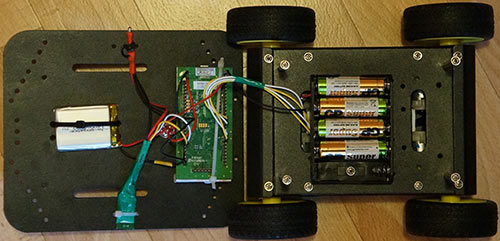
Wiring diagram:
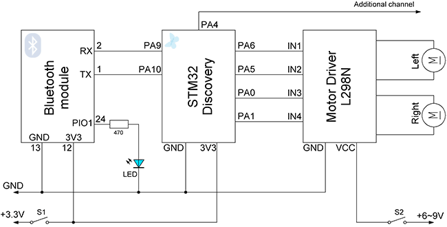
Power supply - is separated, for the controller board SMT32 I used Li-Po battery 3.7V 1400 mAh. To power motors - 5pcs AA batteries (you can use two series-connected Li-Po battery).
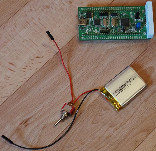
The power switch is soldered to the battery
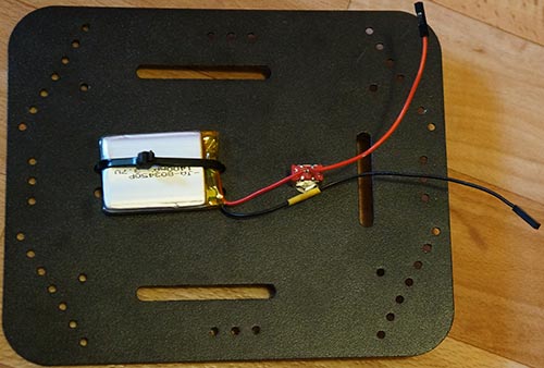
Battery is secured with a clamp, and the power switch installed in a regular place 4WD platform.
Motor driver L298N board I placed in compartment with the motors and closed the regular cover:
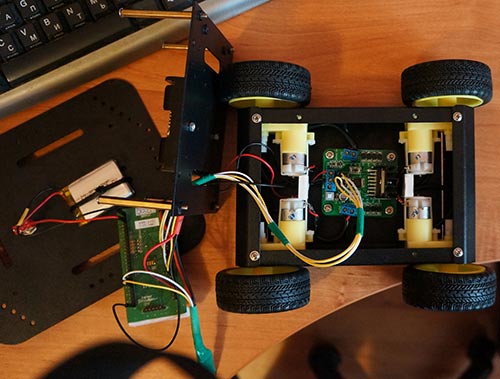
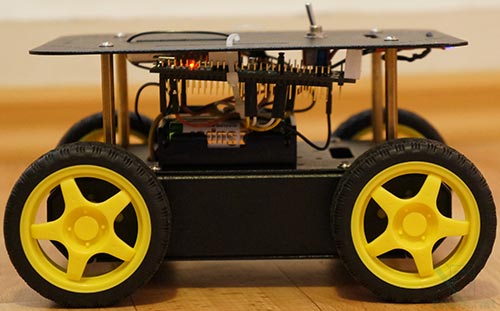
Construction with removed top cover:
Fully assembled:
Software
The program for STM32 Discovery was written in CooCox CoIDE. Full project for CoIDE you can download below. The program includes the following components:
USART - to communicate with the Bluetooth module;
TIM - to generate a PWM signal to the L298N and for time samples;
and also used interrupts (receive data and timing), and read/write Flash memory of STM32.
File main.c:
/*	Wiring:
 *  PA9 - to Bluetooth module RX (pin 2), PA10 - to Bluetooth module TX (pin 1)
 *  PA5 - to IN2 Motor Driver L298N, PA6 (TIM3) - to IN1 Motor Driver L298N (Left Motor)
 *  PA1 - to IN4 Motor Driver L298N, PA0 (TIM2) - to IN3 Motor Driver L298N (Right Motor)
 *  PA4 - to Additional  Channel
 */

#include "stm32f10x_usart.h"
#include "stm32f10x_rcc.h"
#include "stm32f10x_gpio.h"
#include "stm32f10x_tim.h"
#include "misc.h"


void NVIC_Configuration(void);
void GPIO_Configuration(void);
void USART_Configuration(void);
void USART1_IRQHandler(void);
void UARTSend(const unsigned char *pucBuffer, unsigned long ulCount);
uint32_t flash_read(uint32_t address);

char L_Data[5];       	// array data for left motor
uint8_t L_index = 0;    // index of array L
char R_Data[5];       	// array data for right motor
uint8_t R_index = 0;    // index of array R
char H_Data[1];       	// array data for additional channel
uint8_t H_index = 0;    // index of array H
char F_Data[8];       	// array data for  Flash
uint8_t F_index = 0;    // index of array F

char command;         	// command
char incomingByte;
int valueL, valueR;     // PWM value M1, M2

//#define autoOFF 2500  	// milliseconds after which the robot stops when the connection
#define cmdL 'L'  		// UART-command for left motor
#define cmdR 'R'  		// UART-command for right motor
#define cmdH 'H'  		// UART-command for additional channel (for example Horn)
#define cmdF 'F'  		// UART-command for Flash operation
#define cmdr 'r'  		// UART-command for Flash operation (read)
#define cmdw 'w'  		// UART-command for Flash operation (write)

#define FLASH_KEY1		((uint32_t)0x45670123)
#define FLASH_KEY2		((uint32_t)0xCDEF89AB)
#define FLASH_PAGE		((uint8_t)0x7F)

int main(void)
{
	GPIO_Configuration();
	usart_rxtx();
	PWM_Init1();
	PWM_Init2();
	Timer_Init();

	while(1)
	{
	}
}

void GPIO_Configuration(void)
{
	RCC_APB2PeriphClockCmd(RCC_APB2Periph_GPIOA, ENABLE);

	GPIO_InitTypeDef GPIO_Config;

	/* pin - motor rotation for L298N */
	GPIO_Config.GPIO_Pin = GPIO_Pin_5;
	GPIO_Config.GPIO_Mode = GPIO_Mode_Out_PP;
	GPIO_Config.GPIO_Speed = GPIO_Speed_2MHz;
	GPIO_Init(GPIOA, &GPIO_Config);

	/* pin - motor rotation for L298N */
	GPIO_Config.GPIO_Pin = GPIO_Pin_1;
	GPIO_Config.GPIO_Mode = GPIO_Mode_Out_PP;
	GPIO_Config.GPIO_Speed = GPIO_Speed_2MHz;
	GPIO_Init(GPIOA, &GPIO_Config);

	/* pin - additional channel */
	GPIO_Config.GPIO_Pin = GPIO_Pin_4;
	GPIO_Config.GPIO_Mode = GPIO_Mode_Out_PP;
	GPIO_Config.GPIO_Speed = GPIO_Speed_2MHz;
	GPIO_Init(GPIOA, &GPIO_Config);
}

void PWM_Init1(void)
{
	// Initialization TIM2
	RCC_APB1PeriphClockCmd(RCC_APB1Periph_TIM2, ENABLE);

	GPIO_InitTypeDef GPIO_Config;

	GPIO_Config.GPIO_Pin = GPIO_Pin_0;
	GPIO_Config.GPIO_Mode = GPIO_Mode_AF_PP;
	GPIO_Config.GPIO_Speed = GPIO_Speed_2MHz;
	GPIO_Init(GPIOA, &GPIO_Config);

	TIM_TimeBaseInitTypeDef TIM_BaseConfig;
	TIM_OCInitTypeDef TIM_OCConfig;

	TIM_BaseConfig.TIM_Prescaler = (uint16_t) (SystemCoreClock / 1000000) - 1;
	TIM_BaseConfig.TIM_Period = 255;
	TIM_BaseConfig.TIM_ClockDivision = 0;
	TIM_BaseConfig.TIM_CounterMode = TIM_CounterMode_Up;
	TIM_TimeBaseInit(TIM2, &TIM_BaseConfig);

	TIM_OCConfig.TIM_OCMode = TIM_OCMode_PWM1;
	TIM_OCConfig.TIM_OutputState = TIM_OutputState_Enable;
	TIM_OCConfig.TIM_Pulse = 0;
	TIM_OCConfig.TIM_OCPolarity = TIM_OCPolarity_High;

	TIM_OC1Init(TIM2, &TIM_OCConfig);

	TIM_OC1PreloadConfig(TIM2, TIM_OCPreload_Enable);
	TIM_ARRPreloadConfig(TIM2, ENABLE);

	TIM_Cmd(TIM2, ENABLE);		// Start timer TIM3
}

void PWM_Init2(void)
{
	// Initialization TIM3
	RCC_APB1PeriphClockCmd(RCC_APB1Periph_TIM3, ENABLE);

	GPIO_InitTypeDef GPIO_Config;

	GPIO_Config.GPIO_Pin = GPIO_Pin_6;
	GPIO_Config.GPIO_Mode = GPIO_Mode_AF_PP;
	GPIO_Config.GPIO_Speed = GPIO_Speed_2MHz;
	GPIO_Init(GPIOA, &GPIO_Config);

	TIM_TimeBaseInitTypeDef TIM_BaseConfig;
	TIM_OCInitTypeDef TIM_OCConfig;

	TIM_BaseConfig.TIM_Prescaler = (uint16_t) (SystemCoreClock / 1000000) - 1;
	TIM_BaseConfig.TIM_Period = 255;
	TIM_BaseConfig.TIM_ClockDivision = 0;
	TIM_BaseConfig.TIM_CounterMode = TIM_CounterMode_Up;
	TIM_TimeBaseInit(TIM3, &TIM_BaseConfig);

	TIM_OCConfig.TIM_OCMode = TIM_OCMode_PWM1;
	TIM_OCConfig.TIM_OutputState = TIM_OutputState_Enable;
	TIM_OCConfig.TIM_Pulse = 0;
	TIM_OCConfig.TIM_OCPolarity = TIM_OCPolarity_High;

	TIM_OC1Init(TIM3, &TIM_OCConfig);

	TIM_OC1PreloadConfig(TIM3, TIM_OCPreload_Enable);
	TIM_ARRPreloadConfig(TIM3, ENABLE);

	TIM_Cmd(TIM3, ENABLE);		// Start timer TIM3
}

void Timer_Init(void)
{
	uint32_t st_address = FLASH_BASE + FLASH_PAGE * 1024;
	uint8_t sw_autoOFF = flash_read(st_address);

	if(sw_autoOFF == '1'){
		char var_Data[4];

		var_Data[0] = flash_read(st_address)>>8;
		var_Data[1] = flash_read(st_address)>>16;
		var_Data[2] = flash_read(st_address)>>24;
		uint16_t autoOFF = atoi(var_Data)*100;

		// Initialization TIM6
		RCC_APB2PeriphClockCmd(RCC_APB2Periph_GPIOC, ENABLE);
		RCC_APB1PeriphClockCmd(RCC_APB1Periph_TIM6, ENABLE);

		TIM_TimeBaseInitTypeDef TIM_BaseConfig;

		TIM_BaseConfig.TIM_Prescaler = (uint16_t) (SystemCoreClock / 1000) - 1;		// 1кГц
		TIM_BaseConfig.TIM_Period = autoOFF;
		TIM_TimeBaseInit(TIM6, &TIM_BaseConfig);

		TIM_ITConfig(TIM6, TIM_IT_Update, ENABLE);

		TIM_Cmd(TIM6, ENABLE);

		NVIC_EnableIRQ(TIM6_DAC_IRQn);		// Turn on timer interrupt
	}
	else{
		TIM_Cmd(TIM6, DISABLE);
		NVIC_DisableIRQ(TIM6_DAC_IRQn);		// Turn off timer interrupt
	}
}

void TIM6_DAC_IRQHandler()
{
	if (TIM_GetITStatus(TIM6, TIM_IT_Update) != RESET)
	{
	  TIM_ClearITPendingBit(TIM6, TIM_IT_Update);
	  Control4WD(0,0,0);				      // send command Stop Car
	}
}

void USART1_IRQHandler(void)
{
	if ((USART1->SR & USART_FLAG_RXNE) != (u16)RESET)
	{
		TIM_SetCounter(TIM6, 0);			  // reset timer TIM6

		incomingByte = USART_ReceiveData(USART1);

		if(incomingByte == cmdL) {        	  // if received data for left motor L
			command = cmdL;					  // current command
			memset(L_Data,0,sizeof(L_Data));  // clear array
			L_index = 0;                      // resetting array index
		}
		else if(incomingByte == cmdR) {
			command = cmdR;
			memset(R_Data,0,sizeof(R_Data));
			R_index = 0;
		}
		else if(incomingByte == cmdH) {
			command = cmdH;
			memset(H_Data,0,sizeof(H_Data));
			H_index = 0;
		}
		else if(incomingByte == cmdF) {
			command = cmdF;
			memset(F_Data,0,sizeof(F_Data));
			F_index = 0;
		}
		else if(incomingByte == '\r') command = 'e';  // end of line
		else if(incomingByte == '\t') command = 't';  // end of line for Flash op

		if(command == cmdL && incomingByte != cmdL){
			L_Data[L_index] = incomingByte;
			L_index++;
		}
		else if(command == cmdR && incomingByte != cmdR){
			R_Data[R_index] = incomingByte;
			R_index++;
		}
		else if(command == cmdH && incomingByte != cmdH){
			H_Data[H_index] = incomingByte;
			H_index++;
		}
		else if(command == cmdF && incomingByte != cmdF){
			F_Data[F_index] = incomingByte;
			F_index++;
		}
		else if(command == 'e'){
			Control4WD(atoi(L_Data),atoi(R_Data),H_Data);
		}
		else if(command == 't'){
			Flash_Op(F_Data[0],F_Data[1],F_Data[2],F_Data[3],F_Data[4]);
		}
	}
}

void usart_rxtx(void)
{
	RCC_APB2PeriphClockCmd(RCC_APB2Periph_USART1, ENABLE);
	NVIC_Configuration();
	USART_Configuration();
	USART_ITConfig(USART1, USART_IT_RXNE, ENABLE);
}

/* Initialization USART for Bluetooth connecting */
void USART_Configuration(void)
{
	GPIO_InitTypeDef GPIO_InitStructure;

	/* USART1 Tx (pin PA.09) push-pull  */
	GPIO_InitStructure.GPIO_Pin = GPIO_Pin_9;
	GPIO_InitStructure.GPIO_Mode = GPIO_Mode_AF_PP;
	GPIO_InitStructure.GPIO_Speed = GPIO_Speed_2MHz;
	GPIO_Init(GPIOA, &GPIO_InitStructure);

	/* USART1 Rx (PA.10) floating pin */
	GPIO_InitStructure.GPIO_Pin = GPIO_Pin_10;
	GPIO_InitStructure.GPIO_Mode = GPIO_Mode_IN_FLOATING;
	GPIO_Init(GPIOA, &GPIO_InitStructure);


	USART_InitTypeDef USART_InitStructure;

	USART_InitStructure.USART_BaudRate = 9600;		// Baud rate
	USART_InitStructure.USART_WordLength = USART_WordLength_8b;
	USART_InitStructure.USART_StopBits = USART_StopBits_1;
	USART_InitStructure.USART_Parity = USART_Parity_No;
	USART_InitStructure.USART_HardwareFlowControl = USART_HardwareFlowControl_None;
	USART_InitStructure.USART_Mode = USART_Mode_Rx | USART_Mode_Tx;

	USART_Init(USART1, &USART_InitStructure);

	/* Turn On USART1 */
	USART_Cmd(USART1, ENABLE);
}

/* Initialization interrupt from USART */
void NVIC_Configuration(void)
{
	NVIC_InitTypeDef NVIC_InitStructure;

	/* Turn On interrupt from USARTx */
	NVIC_InitStructure.NVIC_IRQChannel = USART1_IRQn;
	NVIC_InitStructure.NVIC_IRQChannelPreemptionPriority = 0;
	NVIC_InitStructure.NVIC_IRQChannelSubPriority = 0;
	NVIC_InitStructure.NVIC_IRQChannelCmd = ENABLE;
	NVIC_Init(&NVIC_InitStructure);
}

void Flash_Op(char FCMD, uint8_t z1, uint8_t z2, uint8_t z3, uint8_t z4){
	uint32_t st_address = FLASH_BASE + FLASH_PAGE * 1024;

	if(FCMD == cmdr){		// if Flash data read command
		uint8_t v1,v2,v3,v4;

		v1 = flash_read(st_address);
		v2 = flash_read(st_address)>>8;
		v3 = flash_read(st_address)>>16;
		v4 = flash_read(st_address)>>24;

		UARTSend("FData:",6);	// send Flash data
		uart_write_var(v1);
		uart_write_var(v2);
		uart_write_var(v3);
		uart_write_var(v4);
		UARTSend("\r\n",2);		// mark the end of the transmission of data Flash
	}
	else if(FCMD == cmdw){		// if Flash data write command
		flash_write_variables(z1, z2, z3, z4);
		Timer_Init();			// reinitialize the timer
		UARTSend("FWOK\r\n",6);	// send a message that the data is successfully written to Flash
	}
}

void Control4WD(int mLeft, int mRight, uint8_t Horn){

	uint8_t directionL, directionR;       // direction of motor rotation L298N

	if(mLeft > 0){
		valueL = mLeft;
		directionL = 0;
	}
	else if(mLeft < 0){
		valueL = 255 - abs(mLeft);
		directionL = 1;
	}
	else {
	    directionL = 0;
		valueL = 0;
	}

	if(mRight > 0){
		valueR = mRight;
		directionR = 0;
	}
	else if(mRight < 0){
		valueR = 255 - abs(mRight);
		directionR = 1;
	}
	else {
		 directionR = 0;
		 valueR = 0;
	}

	if(directionL == 1) {		// set direction of left motor rotation
		GPIO_WriteBit(GPIOA,GPIO_Pin_5,Bit_SET);
	}
	else {
		GPIO_WriteBit(GPIOA,GPIO_Pin_5,Bit_RESET);
	}

	if(directionR == 1) {		// set direction of right motor rotation
		GPIO_WriteBit(GPIOA,GPIO_Pin_1,Bit_SET);
	}
	else {
		GPIO_WriteBit(GPIOA,GPIO_Pin_1,Bit_RESET);
	}

	TIM2->CCR1 = valueR;		// set speed for left motor
	TIM3->CCR1 = valueL;		// set speed for right motor

	if(Horn == 1){
		GPIO_WriteBit(GPIOA,GPIO_Pin_4,Bit_SET);		// additional channel
	}
	else{
		GPIO_WriteBit(GPIOA,GPIO_Pin_4,Bit_RESET);
	}
}

void uart_write_var(uint8_t data) {
	USART_SendData(USART1, (uint8_t) data);
    while(USART_GetFlagStatus(USART1, USART_FLAG_TC) == RESET)
    {
    }
}

void UARTSend(const unsigned char *pucBuffer, unsigned long ulCount)
{
    //
    // Loop while there are more characters to send.
    //
    while(ulCount--)
    {
        USART_SendData(USART1, (uint16_t) *pucBuffer++);
        /* Loop until the end of transmission */
        while(USART_GetFlagStatus(USART1, USART_FLAG_TC) == RESET)
        {
        }
    }
}

uint8_t flash_ready(void) {
	return !(FLASH->SR & FLASH_SR_BSY);
}

/* erase page Flash*/
void flash_erase_page(uint32_t address) {
	FLASH->CR|= FLASH_CR_PER;
	FLASH->AR = address;
	FLASH->CR|= FLASH_CR_STRT;
	while(!flash_ready())
		;
	FLASH->CR&= ~FLASH_CR_PER;
}

/* Unlock Flash */
void flash_unlock(void) {
	FLASH->KEYR = FLASH_KEY1;
	FLASH->KEYR = FLASH_KEY2;
}

/* Lock Flash */
void flash_lock() {
	FLASH->CR |= FLASH_CR_LOCK;
}

/* Write to Flash */
void flash_write(uint32_t address,uint32_t data) {

	FLASH->CR |= FLASH_CR_PG;
	while(!flash_ready())
		;
    *(__IO uint16_t*)address = (uint16_t)data;
	while(!flash_ready())
		;
	address+=2;
	data>>=16;
    *(__IO uint16_t*)address = (uint16_t)data;
	while(!flash_ready())
		;
	FLASH->CR &= ~(FLASH_CR_PG);
}

/* Read Flash */
uint32_t flash_read(uint32_t address) {
	return (*(__IO uint32_t*) address);
}

/* Write 4xbyte to Flash*/
void flash_write_variables(uint8_t var0, uint8_t var1, uint8_t var2, uint8_t var3){
	uint32_t wr_data = var3<<24 | var2<<16 | var1<<8 | var0;
	uint32_t st_address = FLASH_BASE + FLASH_PAGE * 1024;

	flash_unlock();
	flash_erase_page(st_address);
	flash_lock();

	flash_unlock();
	uint16_t tmp;
	for(tmp=0;tmp<1024;tmp+=4)
		flash_write(st_address+tmp,wr_data);
	flash_lock();
}
Arduino board by USART from the Bluetooth module receives data ready for the left and right engine. All basic calculations are performed in the Android application.
Download full project for CooCox CoIDE with source codes
Author: Koltykov A.V.