


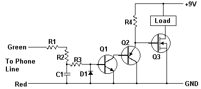
Cut Phone Line Detector
A while ago I got an email asking for the schematic of a circuit to detect cut phone lines. It didn't take me long to find this circuit in Electronics Now. When the circuit detects that a phone line has been cut, it activates a MOSFET which can be used to drive a relay, motor, etc. It can also be connected to a security system.
Schematic
Parts
Part
Total Qty.
Description
Substitutions
R1, R2, R3
3
22 Meg 1/4 W Resistor
R4
1
2.2 Meg 1/4 W Resistor
C1
1
0.47uF 250V Mylar Capicitor
Q1
1
2N3904 Transistor
2N2222
Q2
1
2N3906 Transistor
Q3
1
IRF510 Power MOSFET
D1
1
1N914 Diode
Load
1
See "Notes"
MISC
1
Wire, Phone Connectors, Circiut Board
Notes
1. The "Load" can be a relay, lamp, motor, etc. The circuit can also be connected to a security system to sound an alarm in case the phone line is cut.
2. If the circuit is connected to a security system or other circuit, both circuits must be electrically isolated from each other using an opto-isolator, relay, etc. This also means that the Cut Phone Line Detector must be powered by a seperate 9V supply.