The Link 4+0 – Internal Intercom
Author: Austin Hellier, Wollongong City, Australia © 1997-2003 (26 Nov 2003)
This version of the Link provides four internal intercom phones with no outside line access.

The Link 4+0
This version of the Link is for those who really need a good cheap intercom that will work reliably, but without access to an outside Telco line. This could be in a pre school, a hobby farm or a small workshop or factory, where external phone traffic needs to be kept separate and protected from phone abusers and kids playing around… It follows mainly the principals of the Link pulse dial circuit, but with the modifications and additions of the Link A2B+1 for DTMF dialing.
Circuit Explanation
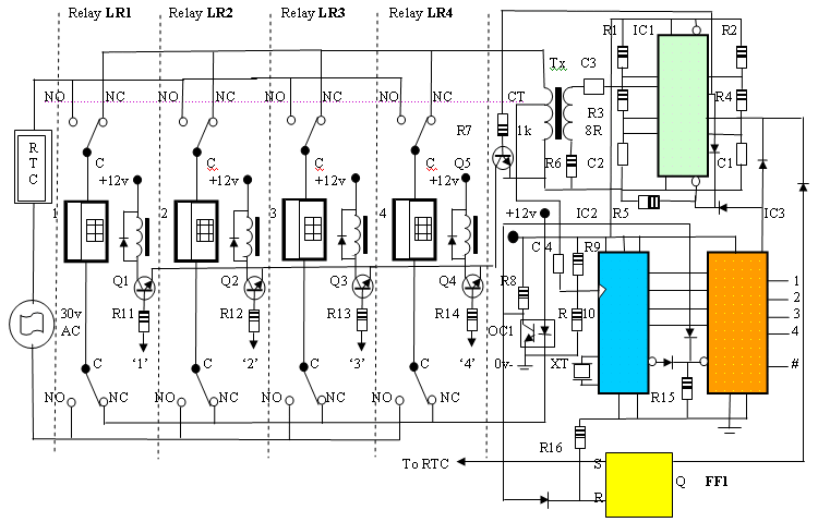
Basically what I’ve done is remove the OSL relay and the flip flop (FF2) that controlled its activation and release, and added an extra two internal handsets and their associated relays and components. FF1 (as part of the Ring Trip Circuit or RTC) is still there, but is now shown down the bottom of the diagram for simplicity’s sake. Internal wiring for the RTR relay is as per the Link A2B circuit. When any phone is picked up off hook and a number from 1 to 4 on the keypad is pressed, the DTMF decoder chip (IC2) decodes this into IC3 (1 x 16 decoder) and the output of IC3 is then fed to the appropriate base resistor of Q1 to Q4 (R11 through R14).
Pin 11 of IC3 goes low, removing the high from pins 12 and 8 of IC1 and impulsing of the selected line relay (LR1 to LR4) begins, via driver transistor Q5 and the appropriate buffer transistor (Q1 to Q4). When the called party answers the call, the RTC circuit ‘trips’ the ring current, impulsing along with the ring tone is halted, and the conversation can proceed. When the conversation is completed and both phones are hung up, the collector of OC1’s phototransistor goes high and resets both FF1 and IC3. Pin 11 of IC3 goes high again, halting the impulsing action of IC1 but providing dial tone from pin 5 in the reset state, ready for the next call. One extra nifty little feature involves the # output (pin 14 of IC3). If you connect this to the set (S) input of FF1, you can halt the ringer if someone calls your extension while you’re away. You can pick up another extension anywhere else and press the # key and effectively ‘pick up’ the call. This feature prevents the other phone from continuing to ring and also halts the ring tone from overpowering your conversation. In principal, it follows very closely the features of the Link pulse dialing version, except that there’s only a two wire circuit between each handset and the ‘black box’ switcher. In reality, tone dialing is more efficient, and you could easily use some of the other unused outputs of IC3 for remote control purposes (turning on sprinklers or low voltage garden lights, door entry systems etc.)
I hope that you have as much fun building and using these circuits as I did in designing them AH – Downunder.


