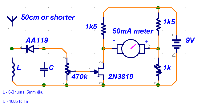
Field-strength meter

Original source:
I saw this circuit in an old issue of "73 Radio Electronics". I built it, but it didn't work well, so I changed a few components to get better sensitivity.Description:
This is a very straightforward circuit. The first stage acts as a crystal receiver. Use a germanium detector diode (like 1N34, but AA119 is much more common in Europe), a silicon one won't do. The frequency is determined by L and C. For the FM band and VHF, wind a coil 5mm in diameter, 6-8 turns of coated wire 1mm thick. You can always vary the frequency by spacing the turns a bit looser or tighter. C is much less critical. Something around 100p is preferable, though.The second stage is based around the versatile 2N3819 JFET high-impedance amplifier. With the 470k potentiometer you can adjust sensitivity of the circuit. The trimmer is used to zero the meter. Use any old 50mA or slightly smaller ammeter from the junk box.
Problems:
You can't expect great performance from such a simple detector-based meter. Sensitivity is just adequate enough to get a basic idea of the power that your transmitter is capable of.Possible uses:
Use the field-strength meter to find out when a transmitter is operating at optimal power. It can be very handy when aligning stages (like in case of the 4W transmitter) or experimenting with different antennas.


