


Smooth Tone Clickless CW Sidetone Generator
(C) G. Forrest Cook 2000, 2003, 2004
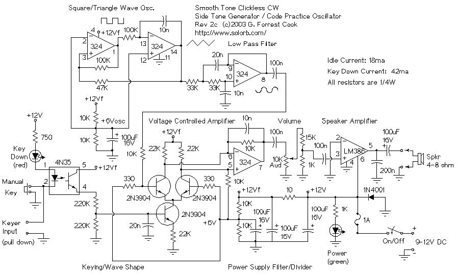
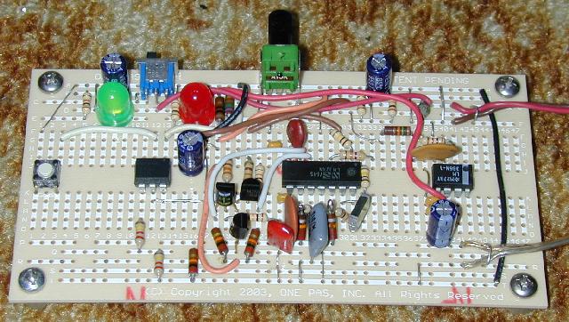
Rev 2c prototype on OnePas
OP840B circuit board
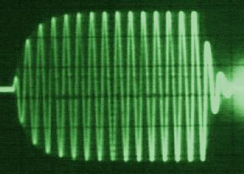
Wave form of one morse code "dit"
INTRODUCTION
November 4, 2000
Updated March 1, 2004
This circuit is about as good as it gets for generating morse code tones. It may be used as a code practice oscillator, a tone generator for a keyer, or a sidetone oscillator for a transmitter.
Feng shuei is the Chinese art of arranging objects in buildings, it is based on many practical ideas. One important concept of feng shuei is the rounding of sharp corners. Think of this circuit as a form of electronic audio feng shuei ;-).
One may think that this is a lot of circuitry just to make simple beep tones, but the real value of the circuit is that it sounds very smooth when compared to a clicky and harsh-toned square wave code oscillator. This circuit won't hurt your ears, even with extended use.
There are other applications for a clickless beeper, one reader was interested in cranking the frequency into the ultrasonic range for use as a dog training device.
The tone quality sounds just like a well shaped CW radio signal, minus the radio noise, of course. Morse code is much easier to listen to when the waveform is smooth, both the sine wave and the keyed envelope are smooth in this case.
Careful readers may notice the lack of a pitch control, this is mainly to keep the circuit simple. The components in the circuit shown produce a 500 hz tone. Changing the pitch requires the use of different part values on both the oscillator and low pass filter sections.
For a different pitch, change the value of the capacitor between pins 13 and 14 of the LM324, and change the two 33K resistors on pins 14 and 9 of the LM324, both resistors should be the same value. An easy, empirical way to find the filter resistor values is to wire in a ganged dual 100K potentiometer in place of the two resistors, tune until a good sine wave is achieved, and measure the resistance on the potentiometer. Substitute the nearest fixed value resistors into the circuit.
A three pole, multi-position switch can be used to select a number of different tones. Each tone requires a specific oscillator capacitor and pair of equal-value filter resistors.
This is revision two of the circuit, changes include the addition of the LM386 audio amplifier IC for greater audio volume, and electrical isolation of the keying input via the 4N35 opto-isolator. The isolation makes the circuit more immune to damage from static electricity zaps on the key.
To further purify the sine wave tone, you can mount a speaker in a tube and cut the tube so that it resonates at around 500 hz with the speaker in place. The resonant tube will also increase the volume.
If the circuit is to be used as a transceiver sidetone generator, remove the LM386 IC and feed the signal from the volume pot into the transceiver's audio circuitry.
Theory
This circuit is essentially a minimal version of an analog music synthesizer that is hard-wired for making morse code tones.
The oscillator section produces a fixed frequency triangle wave on LM324 pin 14, that is fed into a low pass filter to get a sine wave on LM324 pin 8. A triangle wave can be thought of as a series of sine waves with decreasing amplitudes as the frequency increases. The low pass filter simply removes the upper harmonics and passes the fundamental sine wave frequency through.
The sine wave is sent to a voltage controlled amplifier which is modulated with a keying envelope. The keying envelope is generated by smoothing out the square wave keyed signal on the 4N32 emitter with the 100K/20n (.02uF) capacitor/resistor low pass filter on the base of the lower transistor. The two 10K resistors in series with the 4N32 set the envelope's upper and lower voltage to 6V and 0V.
Keying of the circuit is performed either by the manual key input, or via the keyer input, which can be used to connect the circut to a morse code keying chip. To use the keying input, an active low open collector driver should be used.
The audio signal comes out of LM324 pin 7, it connects to a 10K volume potentiometer and an attenuator made with two resistors. The attenuated audio is then fed to the LM386 audio amplifier.
The 200n capacitor on the audio output prevents the LM386 from generating RF oscillations, which it likes to do. I originally tried using the series R-C network that is normally shown on LM386 application notes, but the LM386 would break into RF oscillations.
The circuit nodes marked +12Vf are all connected together, this is the filtered +12V line. The +12V line is filtered through a 10 ohm resistor and across a 100uF capacitor, those components remove audio noise that may be present on the +12V supply.
A careful observer will notice that there are two identical +6V divider chains, one for the oscillator and one for the VCA. I started with a single divider, but the oscillator tone changed when the circuit was keyed. An op-amp divider could also be used, but the cost and current consumption would probably both go up.
Construction
The Sidetone Generator was built on a OnePas brand prototype circuit board. The wiring pattern on this board is the same as that found on many wireless prototype socket boards. This makes it possible to build a temporary circuit on the plug board and transfer it to a more permanent layout on the OnePas board. It should be fairly easy to copy this circuit layout just by looking at the photograph, there are a few trace cuts and insulated jumpers on the bottom of the board. Also, a few extra holes were drilled in the board to hold the potentiometer.
A custom printed circuit board would be the logical next step in the circuit's evolution, however I have not layed out a PC board yet.
Source:www.solorb.com