1-Transistor FM Transmitter

| R1 | 27k |
| R2 | 56k |
| R3 | 12k |
| R4 | 100 |
| C1 | 1u |
| C2, C3 | 470p |
| C4 | 6 to 10p |
| C5 | 1-30p trimmer |
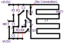
| L1 | etched on PCB or a center-tapped coil 5mm in diameter, 6-8 turns of enamel-coated wire 1mm thick |
| Mic | Electret microphone |
| Q1 | 2N3564, 2N5225 (other general-purpose NPN transistors will work, too) |

 Description:
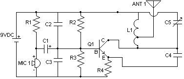
A truly minimalist circuit. Performance is relatively poor and stability is a problem. Q1 modulates the signal and acts as an oscillator. L1 and C5 determine the frequency. Decrease C5 for a higher frequency and vice-versa.
You won't get a long range transmission with this one. The author claims 50-500 feet. A lot depends on the antenna. It must be made of stiff wire or else the frequency will change as you move the antenna. Experiment with different lengths to get the maximum range. 50cm or less should work reliably most of the time. A longer antenna might give even better range but if you exaggerate, the circuit will begin to oscillate and performance will drop dramatically. A regular telescope whip should work, too.
Problems:
If assembling the circuit on perf board, all connections should be kept short. You'll probably notice that this transmitter is not particularly stable. It might be difficult to tune a receiver to it as the operating frequency will vary a little with time and temperature or if someone steps close to the antenna.
Possible uses:
Room/telephone bug, but that's illegal, I guess. This is a nice circuit to learn the basics, though.


