Category: Main page » Audio Preamplifiers

Simple High Quality Preamp For Hi-Fi


Introduction

Note: Please see the updated version of the Hi-Fi preamp, shown in Project 88 www.sound.westhost.com. The new version has PCBs available, and is recommended for the best sound quality. If you need tone controls, you should see Project  97 www.sound.westhost.com which has excellent sound quality, and includes tone controls

Much has been made of preamps, but provided a few simple precautions are taken, they are very simple to design, and high performance is almost assured using modern op-amps. For those to whom op-amps are an anathma, please skip this section, AFTER reading the next two paragraphs, please.

While op-amps have something of a bad name in audiophile circles, what must be remembered is that between the music leaving the musician's instrument and arriving at your ears, there is every probability that it has already passed through somewhere between 10 to 100 op-amps - in the mixer (usually more than once), in external effects units, tape machines (analogue or digital), and finally in the CD player itself.

Many of these are not as good as the ones used in this design, and to dismiss a design simply because it uses an op-amp or three is to finish up spending far more than is necessary to obtain the same sonic quality. This is not to say that a good valve preamp (for example) will not sound better (or perhaps just different), but the "op-amp sound" is a myth which should not be perpetuated (and this is from someone who uses a valve and op-amp preamp, both of my own design).


Features

For those who are still with me, the preamp featured has optional tone and balance controls which may be omitted if desired (although I do not recommend this generally). The input switching may be extended if needed to accommodate more signal sources, however in this version, no RIAA (phono) input is provided - see the separate Project Page article for a stand-alone phono preamp which can be added if desired.

The tone controls do not use the traditional "Baxandall" feedback design, but are basic passive controls, which offer a modest 6dB of boost and cut at maximum. This may not sound like much (most tone controls offer 12 to 20dB), but in reality is usually quite sufficient for such minor corrections as are usually needed. (Note that these tone controls can also be used in the Project 88 preamp).

NOTE: The tone controls have been changed slightly from the original publication of this circuit.  The treble control should ideally use a 1nF capacitor (10nF was used previously).  As now shown, there will be 3dB of boost or cut at 6kHz and 55Hz with the controls at maximum.  (I did say that they were subtle!)  If the effect is too subtle, increasing the value of the bass and treble caps (100nF and 1nF respectively) will lower the frequency, and vice versa.  Some people may find that the bass control is better with a 47nF capacitor - this will almost certainly be the case with small loudspeaker systems.

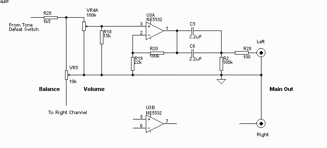
A tape output is provided - this can be left out if not needed, but again I would suggest that it is worthwhile keeping. The following shows the inputs and switching circuitry.

Figure 1
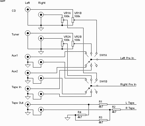
Figure 1.  Inputs, Tape Out and Switching

Construction is not overly critical, but care should be taken to ensure that left and right channel wiring is kept separated wherever possible to prevent crosstalk. All input switching should be performed using an extended shaft rotary switch. This allows all inputs to be shielded in their own section, and reduces the amount of shielded cable required. The input level controls for CD and Tuner inputs allows the levels to be balanced, so that with a little experimenation, it should be possible to switch from one input to any other and retain the same volume. Note that the "traditional" tape monitor switch has not been included, since I suspect it is rarely used these days. If needed, it can easily be accommodated.

The "Tape Out" connectors are wired back to the input amp, so would have had a gain of 2 (6dB) without the attenuator. This also provides useful buffering of the input amp from any "nasties" which could occur (shorted signal leads, etc), and prevents variations in signal when the tape is connected.

Figure 2
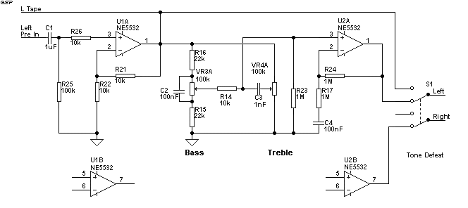
Figure 2- Input Buffer and Tone Controls

Only the left channel is shown in full, the right channel is identical, and uses the "B" halves of the NE5532 op-amps (pinouts are shown for reference). Note that power is connected to the op-amps ...
  • +ve   Pin 8
  • -ve   Pin 4 If connected the wrong way, the op-amps will die !
  • The input stage has a gain of two (6dB), and is also the buffer for the tone controls. The tone control buffer also has a gain of two to make up for losses in the tone control stage (6dB), so the total gain after the tone controls is four (for those frequencies which are boosted to the maximum). Allowing for 2V RMS from a CD player, this is 8V RMS, or a peak swing of 11.3V in either direction (assuming the input level control is fully advanced and maximum boost is applied). This requires a power supply voltage of +/- 15V to ensure that the signal will not clip. Other levels will be considerably below the 2V RMS of the CD player, and are completely safe from clipping.

    Note that the tone controls are almost completely flat when centred - any deviation from flat response is more likely to be mechanical rather than electrical. When switched out, the controls and the buffer amp are removed from the circuit.

    Figure 3
    Figure 3- Balance and Volume, Final Gain Section

    The final section provides the bulk of the gain (12.6dB), and includes the volume and balance controls. The balance control introduces a loss of 2.3dB in the centre position, and has a semi-log characteristic, so fine control about the centre position is very easy and precise. When the control is rotated to one extreme or the other, the opposite channel gains 1dB of signal. Using a gain controlled stage here would lower noise, but this is not expected to be a problem. If your amplifier is of unusually high sensitivity, simply increase the value of R19 - gain of this stage is given by

    Total system gain with all controls (other than tone) at maximum is 18.5dB, so 230mV will drive an amp with a 2V input sensitivity to full power. If more gain is required (which is rather unlikely), this may be obtained by reducing the value of R19 in the final output stage (currently 22k). If for example you needed a total gain of 24dB, the value of R19 must be reduced to 12k. Expect noise to increase in proportion as gain is raised.  I have found that with power amps of typical sensitivity (about 27dB gain), an overall preamp gain of 10dB is sufficient with most sources.  This may be achieved by increasing R19 to 82k, so the overall gain will be ...

    If you wanted to, the values of R19 and R20 can be divided by 10 (to 10k and 2.2k as shown).  This may reduce noise by a marginal amount because of the lower impedances.  I have not measured the noise levels in both configurations, but they will be very low either way.

    All potentiometers are linear taper (do not use log pots), and the critical one (Volume) is modified using the principles explained in the project 01.

    Each op-amp should be bypassed with a 10uF/25V electrolytic from each supply lead to ground, and a 100nF capacitor between supply leads (not shown in diagrams). The latter should be as close as practicable to the op-amp supply pins, and the 10uF caps can be almost anywhere you like. The op-amps specified are premium devices, but should be reasonably easy to find. There are better devices, but the overall quality of the 5532 devices used in this design should satisy the most discerning listener. These devices are internally stabilised, and no external capacitor is needed.  Failure to bypass the supplies properly will result in high frequency oscillation, which will cause the sound to be distorted - this will be subtle, but is insidious and makes the preamp sound terrible compared with another.  This is something to avoid.

    Note that all op-amps (except the tone buffer) operate with DC gain. To eliminate this would have required the use of electrolytic caps in the signal path, something I wanted to avoid. This will cause slight DC offsets to appear at the op-amp outputs, but these will be in the order of a few millivolts only.

    Using 2 x 2.2uF capacitors provides a low frequency -3dB point of less than 5Hz with a 10k ohm load. This should be suitable for all known amplifiers. Do not be tempted to delete these caps, as DC - even in small amounts - passed to the power amp is not a good idea !

    The 100 Ohm resistor in the output is designed to prevent any oscillation of the op-amp when connected to coaxial audio leads (some (many?) leads will cause op-amps to oscillate if this is omitted).

    For a suitable power supply, I suggest the use of an external transformer to eliminate any possibility of hum pickup - especially if the phono section is included. A power supply which is suitable is available on the Project Pages (see Project 05). This uses a 16V AC plug-pack type transformer (if you can get one - they're not all that uncommon, but you may need to search a little), and all rectification, filtering and regulation is done within the preamp chassis. If you really want to include the transformer in the chassis, use a toroidal type (20VA is more than enough) to keep magnetic fields to a minimum.


    Construction

    An "off-the-shelf" 1RU (rack unit - 1 3/4" height) rack case is quite roomy enough for everything, or if you have the capability to make your own chassis, do so.

    All input and output connectors are gold plated RCA types (except for power, see below), and the use of 1% metal film resistors is suggested throughout. These are now barely more expensive than carbon, but have a far better noise figure. Likewise, there are no electrolytic caps used in the signal path, but the required values (in some cases) means that you will have a fairly large component to mount.

    All components can be mounted on a piece of perforated prototype board ("Veroboard" or similar), taking care with the orientation of the op-amps and electrolytic capacitors.

    For the power connection, only use the internal mains transformer option if you are absolutely sure that you know what you are doing - mains power is dangerous! In this case, use a standard IEC type male power connector, otherwise, use an XLR ("Cannon") connector for the 12V AC input. These are infinitely more reliable than those horrid little tubular things, and they never fall out. The XLR connections are described in the Power Supply project page.

    Source:www.sound.westhost.com

    Clement Cham 2014-07-11 14:28:14
    This tone circuit i build it before ,sound very good .Low noise ,mid sound very clear ,bass also very strong..if add the super bass circuit ,oh , very perfect...

    [Reply] [Reply with quote]
    ↑ +7 ↓

    Pages: [1]

    Leave a comment

    Your name:
    Your Email:

    Comment:
    Type the characters: *
    captcha
    Refresh