


High Efficiency 12V White LED Driver
Power this project from sunlight with a CirKits solar power circuit board kit.
High Efficiency 12V White LED Driver
(C) G. Forrest Cook February 3, 2006Introduction
DC powered LED lighting circuits can vary from the trivial, with a single LED and a series resistor, to more complicated arrays of LEDs and resistors, to the complicated. Typically, there is a tradeoff between simplicity and efficiency. Also, simpler circuits may produce variable light intensity over a range of voltages, while more complicated circuits can produce a more regulated light level. This circuit is on the complicated end of the spectrum, it runs 8 white LEDs at 25mA of current with only 70mA of supply current at 12V. A high frequency switching regulator us used to reduce the power loss associated with multiple current dropping resistors. LED intensity is fully regulated across the entire operating voltage range.
Specifications
Power Requirements:
Operating Voltage: 10-18V DC
Operating Current: 70mA @ 12V DC (8 LEDs)
Current at low voltage shutoff point: 5mA
Theory
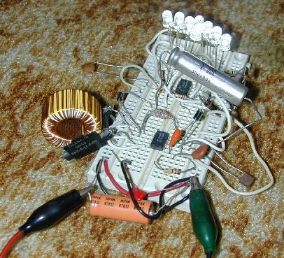
The heart of the circuit is a string of 8 white LEDs. These are wired in series and connected to a current-regulated step-up switching power supply circuit.
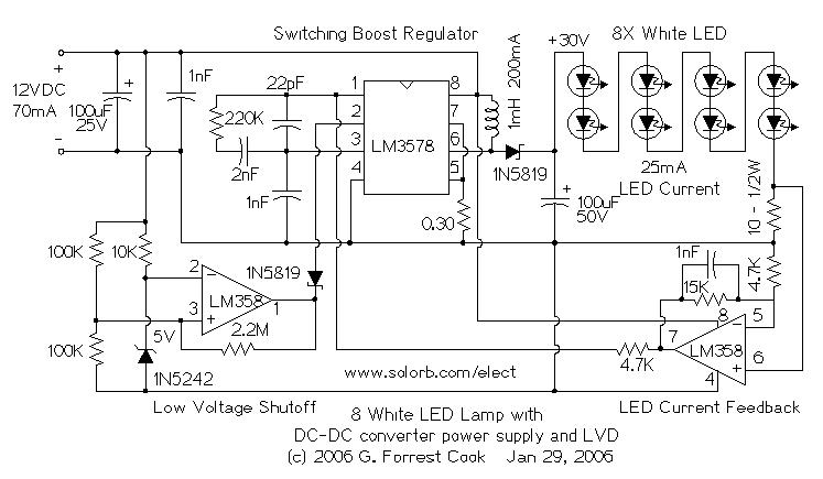
The LM3578 switching regulator and its associated inductor, 1N5819 schottky diode, and 100uF 50V capacitor step the 12V power supply up to approximately 30V DC. The 10 ohm resistor on the cathode end of the LED string develops a voltage that is proportional to the current through the LEDs. This voltage is amplified by half of the LM358 op-amp and sends a negative feedback signal through a 4.7K resistor back to the LM3578. The 15K feedback resistor across the LM358 sets the LED series current, in this case, it is approximately 25mA.
The other half of the LM358 (pins 1,2,3) is wired as a 10V voltage comparator. The 1N5242 zener diode and 10K series resistor produces a steady 5V on pin 2 of the LM358. The two 100K resistors on pin 3 of the LM358 divide the input voltage in half. If the supply voltage drops below 10V, the output of the LM358 drops, and pulls pin 2 of the LM3578 down through a 1N5819 schottky diode, causing the LM3578 to shut down. A schottky diode is used instead of a standard silicon diode in order for the LM3578 pin 2 voltage to go low enough to disable the circuit. Without the low voltage shutdown circuit, the LM3578 current will increase as the supply voltage decreases until the IC self-destructs.
The 2.2M resistor across the LM358 produces a hysteresis effect, the circuit turns off about .25V below where it turns back on, this prevents oscillation around the shutoff threshold. Below the low voltage cutoff point, the circuit will consume about 5mA of current.
An interesting characteristic of this circuit is that it acts as a negative resistance at the power supply terminals. As the supply voltage is increased, the current will drop. The total power consumption stays nearly even across changing input voltage conditions.
The heart of the circuit was inspired by F. Garcia's IR LED video illumination circuit, published in the July 2001 edition of Nuts and Volts magazine. I modified the LED count and feedback circuit, and added the low voltage shutdown feature.
Use
Just connect the circuit to a 12V DC power supply, such as a solar charged lead acid battery. The light will remain constant through the battery voltage change, and the circuit will consume a minimal amount of power.
It is possible to increase the number of LEDs in this circuit to 10 and possibly 12, as the LED count goes up, so does the regulator's output voltage and input current. For higher output voltages, the 100uF 50V capacitor should be changed to a 63V part, a higher current inductor may also be required.
Source:www.solorb.com