


Self Powered Solar Box Furnace
(C) G. Forrest Cook 2002
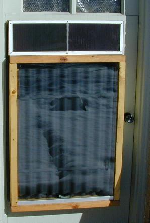
(Photo 1) Solar furnace mounted on an external door |
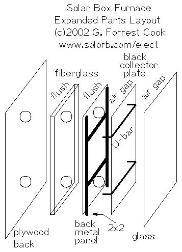
(Figure 1) Expanded parts layout |
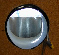
(Photo 3) Warm air exits from the output port on the top |
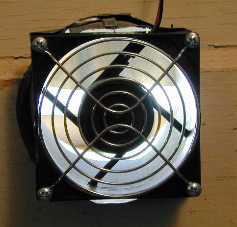
(Photo 2) The fan pushes cold air into the input port on the bottom. |
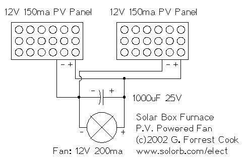
(Figure 2) Schematic
Introduction
This project involves the construction of a self contained solar box furnace (Photo 1). With the constantly rising price of natural gas and heating oil, this project is becoming more and more attractive. I assembled the prototype with materials that I had laying around my workshop. It is suitable for heating up a small room or a detached shed. I use the furnace to warm up my garage, it takes the chill out of a fairly large space on cold sunny days. It is possible to scale this project up to any size. A larger version of this furnace could be used to add a lot of supplemental heat a house.At night, the solar furnace will cause some heat loss due to downward convection of cold air through the box. This convection can be greatly reduced by bringing the input port up to the level of the output port with some right-angle ducting. A U shaped air passage will cause cold air to become trapped in the the bottom of the box at night.
Specifications
Nominal Operating Voltage: 12VDC
Operating Current: 200ma (depending on the fan)
Heat Output: depending on the size of the box, the equivalent
             of a few hundred watts when the box is in full sun.
Some example data was taken with the solar furnace.
On a sunny day with a 10 degree C outdoor temperature, the furnace was able
to increase the interior garage air from 12 degrees C to 29 degrees C.
The fan's air flow rating is 30 cubic feet per minute at full speed.
Theory
This is a self-contained and self-powered device. Sun shining on black metal collector plate is absorbed and converted to heat. Sun shining on the solar panel array powers the fan, which pushes cold air into the bottom of the box (Photo 2). The cold air warms up as it passes over the collector plate, then the warmed air exits from the top of the box (Photo 3).The electronics in this project are quite simple (Figure 2). The solar panel array provides enough current to run a 12V computer fan. The capacitor smooths out the electrical supply to the fan, so that interruptions in the light source don't produce sudden motor speed changes. This should increase the life of the fan bearings.
The insulation at the back of the box prevents heat loss through the cold side. When there is enough sun to heat the box, there is also enough sun to run the fan. No electrical controls are necessary.
A differential temperature control could be added to the fan circuit to insure that the fan never runs when the furnace is not producing useful heat. One big advantage of such as system is that the control can be set to turn on when the box air temperature is a specified number of degrees warmer than the room air. This would allow the furnace to output air that is noticeably warmer than the inside air, and the fan would only intermittantly.
I have built the differential temperature controller, and it does indeed work nicely in this application, it will be the subject of a future article.
Construction
Dimensions depend on the materials that you use, consider the space that you have to mount the box and the materials that you have on hand. My box is approximately 2.5' x 4'.Construct a wood box out of the 2x6 lumber, I used a table saw to cut 3/8" deep slots near the front edge of the 2x6 box sides. This produces a gap for the glass panel to slide into. Screw the 2x6 pieces together to form the box.
A surplus shower door would also make an excellent glass panel since it comes with an aluminum frame and is made of tempered glass. The shower door could be mounted to the front of the 2x6 box and sealed with silicone caulk.
Cut the collector plate so that it fits into the box. The collector plate should be approximately 2" shorter than the interior of the box so that air can pass over the bottom and top. (Figure 1) The paint should be painted flat black, high temperature stove paint is a good choice. Paint both sides of the collector plate for best results.
Bend the two metal bars into a squared U shape, they should hold the metal collector plate inside of the box so that the collector plate has an air gap on both the front and back sides. The U bars should fit snugly into the sides of the box. I placed the bar in a vise and hammered both ends to a 90 degree bend. Drill four 5/64" holes in each bar, 2 holes for connecting to the collector plate, and 2 holes for screwing the bar into the inside of the 2x6 frame. The collector plate is attached to the U bars with 4 sheet metal screws. The U bars are attached to the inside of the 2x6 box with 4 wood screws.
A 2x2 frame should be made in a double H shape (Figure 1), its purpose is to act as a spacer between the back metal panel and the collector plate. Screw the 2x2 frame to the inside of the 2x6 box. In my prototype version, the 2x2 frame was narrower than the box so that it fit within the bent ends of the U bars.
Cut the back metal panel so that it fits exactly inside of the 2x6 box. Using a jig saw, cut holes in the top and bottom center of the back metal panel for the ducts to pass through. Screw the back metal panel to back of the 2x2 frame.
Cut fiberglass insulation material to fit between the back metal panel and the back of the 2x6 box. Cut holes in the fiberglass for the two ducts. Cut the plywood back panel so that it covers the back of the 2x6 box. Cut holes for the 2 ducts in the back panel. It may be best to use some type of high temperature solid insulation instead of fiberglass in order to prevent glass fibers from getting into the air.
Disassemble the box, paint all of the wood pieces with deck type water seal. Clean and paint the collector plate with the flat black paint, let it bake in the sun. Reassemble all of the painted parts.
Apply a bead of silicone caulk around the edge of the glass panel to keep water from getting into the box.
Install the 2 metal ducts into the holes in the back of the box. The ducts should go into the box as far as the back metal panel. Mount the 12V fan to the back of the bottom duct. The duct can be cut lengthwise with a tin snip, about 1" deep. The resulting metal tabs should be spread out and drilled to match the fan mounting holes. Mount the fan on the end of the duct.
Routing of the ducts is specific to your installation. I mounted the box on an exterior wooden door and cut holes in the door for the ducts to pass through. Insulated ducts should be used if the ducts have to pass through an area of cool air.
Mount the solar panels to the top of the box, or somewhere that receives a lot of sun through the day. The panels that I used were surplus amorphous type, I glued them to a fiber board panel with silicone rubber caulk, and mounted the panel on the top of the furnace box.
A commonly available VW/Audi battery maintainer solar panel is also suitable for use in this project. These panels are available on eBay for around $20, one or two of them would work nicely for this project.
Wire the solar panels in parallel with each other, the fan, and the capacitor. All positive leads connect together, all negative leads connect together. Fasten the wire junctions with the two wire nuts.
Alignment
Point the furnace to the South if you live in a Northern climate. If you can, mount the box at an angle so that it faces directly toward the sun at noon during the winter months. In some cases, mounting the box vertically is the only option, usefull heat will be produced as long as the box is in full sun.In my installation, the box is mounted vertically and it is pointed toward the South West. The furnace starts up later in the day than it would if it were pointed due South, but it warms up quickly and provides more heat later in the day.
Use
Just let it run, if the sun shines on the box, warm air will flow out of the top duct. I have used the furnace to warm my garage through several cold seasons, it nicely warms up an otherwise frigid part of the house. This box can pay for itself over time by lowering your utility bills.During the summer months when additional heat is not desired, the glass front of the solar furnace should be covered with a reflective surface such as a piece of plywood or metal. The cover should be painted white to reflect the sun. The the fan can be disconnected to save bearing life.
Parts
2x 12V/150ma amorphous or polysilicon solar panels
1x 12VDC 4" computer fan, approximately 200ma operating current
1x fan finger guard (optional)
1x 1000uF 25V electrolytic capacitor
2x wire nuts
10 feet of #20 stranded hookup wire
1x clear glass pane, 3/8" tempered glass is recommended
2x6 lumber for the box frame
2x2 lumber for the internal spacer frame
plywood or press-board for the back
Corrugated steel roofing material
2 pieces of 1/8" x 1/2" soft steel bar
flat black paint for the metal collector panel, high temperature paint is best
deck type water seal for the wood pieces
1 tube of silicone caulk
fiberglass or high temperature solid insulation
2x 8" lengths of 4" diameter metal ducting
miscellaneous screws
Parts Sources
Local hardware/building supply stores, eBay for solar panels
Source:www.solorb.com