


SPC2 6 Amp Solar Power Center
A kit with the circuit board and parts for this circuit is available from
CirKits.
SPC2 6 Amp Solar Power Center
(C) G. Forrest Cook 2002
Introduction
The SPC2 is a solar power center, it can be used to handle all of the power functions for small 12 Volt solar powered devices. It contains a photovoltaic charge controller and a low voltage load disconnect circuit. The low voltage disconnect has a load on-off switch, and a battery low voltage indicator. By using the SPC2 as the center of a solar powered device, long battery life is assured. The SPC2 can be used for powered lighting systems, radios, and other 12 Volt devices.
The circuit was designed with the following goals:
Single board solution for many solar power uses.
Analog simplicity with common parts for ease of repair.
High efficiency: low loss charging and minimal idle current.
Radio-quiet operation, low frequency charge control switching.
Specifications
Nominal battery voltage: 12V
Maximum solar panel current: 6 Amps
Maximum load current: 6 Amps, more with an external solid-state relay
Night time battery drain current: approximately 10 micro-amps
Temperature compensation for use in variable climates
Radio-quiet operation
See the full SPC2 kit specifications for a more detailed list.
Charge Controller Theory
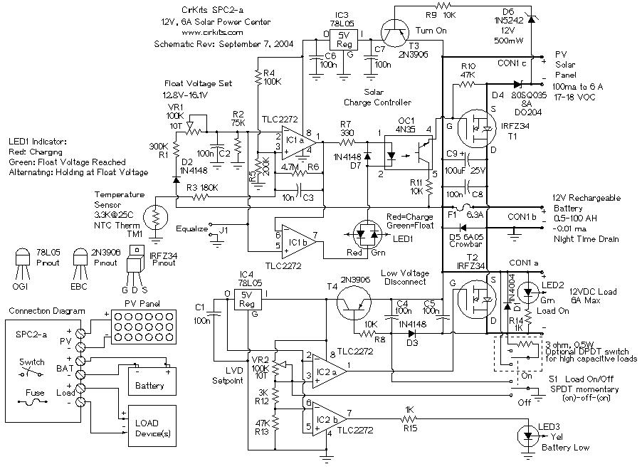
The charge controller is shown in the upper half of the schematic. Transistor T3 turns on power to the rest of the charge controller circuitry when the PV panel input exceeds 12V. Regulator IC3 provides 5 Volts to run the rest of the circuit.
The upper half of IC1 is the heart of the charge controller. It acts as a combined comparator/oscillator circuit. When the battery voltage is well below the float voltage setting, IC1 turns on, this causes the LED to turn red and the 4N35 to turn on. The output of the 4N35 activates FET T1, which connects the solar panel power to the battery. When the float voltage is reached, the circuit oscillates above and below the float voltage setting as the charging current gets switched on and off of the battery. The oscillation frequency is mainly set by the battery charging characteristics and the current that is available from the solar panel. The 10n capacitor across the upper half of IC1 limits the maximum switching frequency. The 4.7M resistor across IC1 causes the circuit to have some hysteresis, seperating the charge/float switch points.
The thermistor modulates the float voltage setting slightly, the full voltage setpoint rises in colder temperatures. The lower half of IC1 always produces the opposite output from the upper half of IC1 for driving the bipolar LED. Shorting the equalize terminals causes the circuit to stay in the charging state, this is useful for occasionally overcharging (equalizing) a battery.
Diode D4 prevents the battery from draining back into the solar panel at night. Diode D5 is a crowbar, if the battery is connected in reverse, it causes the fuse to blow, this saves the rest of the circuitry from destruction.
Low Voltage Disconnect Theory
The low voltage disconnect circuit is shown in the lower half of the schematic. The circuit operates like a solid-state version of a latching relay. Unlike simple under-voltage shutoff devices, when the LVD circuit shuts off, it stays off until it is manually turned back on. This prevents the load from oscillating off and on due to the rise in battery voltage after the load is disconnected.
When the momentary switch is turned on, transistor T4 is turned on. This activates the comparator circuits formed by the two halves of IC2. As long as the battery voltage is above the LVD setpoint, the upper IC2 comparator goes high and FET T2 is switched on. Once the LVD circuit has been turned on, T4 continues to stay on via the current through the 1N4148 diode.
The IC4 regulator provides a reference voltage to compare the battery voltage to. The voltage on IC2 pin 8 tracks the battery voltage. When the battery voltage drops near the shutoff point, the lower half of IC2 turns on, causing the yellow low voltage warning LED to light. When the battery voltage drops further, to the cutoff point, the upper half of IC2 goes low, causing FET T2 to turn off, cutting power to the load. The bias current through the 1N4148 diode also shuts off, T4 turns off, and the rest of the circuitry loses power.
If the LVD circuit is on, switching the momentary switch to off causes the upper half of IC2 to produce a low output, shutting down the LVD circuit as described above. High capacitance loads (above several thousand microfarads) will tend to keep the circuit on for a while when the off switch is pressed. Adding the circuit shown in the dashed box will help to speed up the discharge of the capacitance.
Charge Controller Alignment
Connect the PV panel and battery to the circuit. Turn the float voltage setting fully clockwise, the dual color LED should turn red. Measure the battery voltage with a volt meter. The battery voltage should gradually rise. Leave the circuit connected until the battery voltage has reached or exceeded the fully charged setting, typically around 13.8V at room temperature. Turn the float voltage setting counter clockwise until the LED alternates red and green. Tweak the setting until the LED blinks and the battery voltage is where you want it to be at the full state.
Low Voltage Disconnect Alignment
Connect a variable voltage power supply that can produce 10 to 15 Volts across the battery terminals. Set the supply to 11.0 Volts. Turn the LVD Setpoint pot fully counter-clockwise. Turn the power switch on. The Green power LED should go on. Turn the pot clockwise until the yellow low voltage LED turns on. Slowly turn the pot clockwise until the yellow and green LEDs turn off. Adjust the power supply to 12V and turn the power switch on. Gradually turn the power supply voltage down until the LVD cuts out, you may need to repeat this test while tweaking the pot to set the shutoff point exactly.
Use
Connect a gell cell or wet cell lead acid battery, photovoltaic panel, and a load, such as an automotive tail light, to the circuit.
As sun shines on the solar panel, the circuit will pass charging current to the battery. The dual color LED will turn red while charging is taking place. When the battery voltage rises to the full setpoint, the charging current will be cut off and the LED will turn green. The LED will then alternate from red to green as long as solar power is coming in, and the load is off.
The on/off switch controls the load like a normal power switch. If the battery voltage drops to near the shutoff point, the yellow LED will light up. If the battery voltage drops further, the circuit will shuts the load off, preventing deep discharge of the battery. This greatly extends the life of the battery.
Solar Charge Controller Kits For Sale
A kit version of this solar power center circuit is available from CirKits.Plug: Buying the kit saves you a lot of trouble locating parts and wiring the circuit.
Source:www.solorb.com