An Add-on Current Limiter
Description:
This circuit allows you to set a limit on the maximum output current available from your PSU. It's very useful when you power-up a project for the first time - or carry out a soak-test. By setting an upper limit on the current available from your PSU - you can protect both your power supply - and any device connected to it.
Notes:
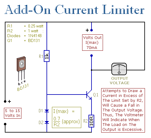
The basic circuit is shown in the first schematic. The two diodes fix the voltage on the base of the Power Transistor at about 1v4. This means that the voltage across R2 is fixed at about 0v7. If R2 is 10 ohms, then the maximum emitter current is (0v7 ч 10) about 70mA.
Since the collector current is always more or less equal to the emitter current - you cannot draw more than 70mA from the output terminals. If you try to do so - the output voltage will fall.

I used a BD131 because that was what I had available. However, any NPN Power Transistor with a similar - or better - spec should work fine. I had no special reason for chosing a 70mA maximum. If you want to set a different current limit - change the value of R2. The formula is in the diagram. Always remember that if you increase the current - you'll also increase the watts.
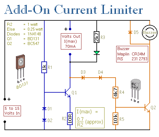
The second schematic has a couple of added features. If you don't want to use a voltmeter on the output - use an LED instead. If the output voltage falls - the LED will dim or extinguish completely. This is enough to let you know that the load on the output is excessive.
Where the Current Limiter is to be left unattended for any length of time - say during a soak-test - the Buzzer is useful. Should a problem develope - and the output voltage fall by 2-volts or more - the circuit will sound the alarm.

Veroboard Layout:
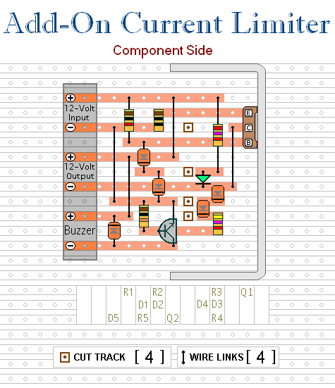
The layout provided is for the second schematic - but it's flexible. If you don't want the LED feature - just leave out the LED and R3. If you don't want the alarm feature - leave out D3, D4, D5, R4, R5 & Q2.

The heatsink is a folded strip of aluminium about 2mm thick, 6cm long and 3cm tall. If you increase significantly the maximum current available from the limiter circuit - you'll probably need to increase the size of the heatsink as well.
The Support material for this circuit includes a detailed guide to the construction of the circuit-board, a parts list, a complete circuit description and more.
Source:www.zen22142.zen.co.uk


