Rectification using a Gyrator Circuit

Notes:
To avoid excess ripple output
on a power
supply feeding a heavy load, usually a large value capacitor is
chosen following the
rectifier. In this
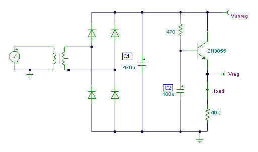
circuit, C1 is only a 470uF capacitor. The gyrator principle
uses
the
effect that the value of
input capacitance
at the base of a transitor is effectively multiplied by the current
gain of the
transistor. Here C2
which is 100u appears at the ouput ( Vreg ) to be 100 x current gain of
the 2N3055 power transistor.
If you assume
a dc current gain of 50, then the smoothing across the
supply, would be as though
you had chosen
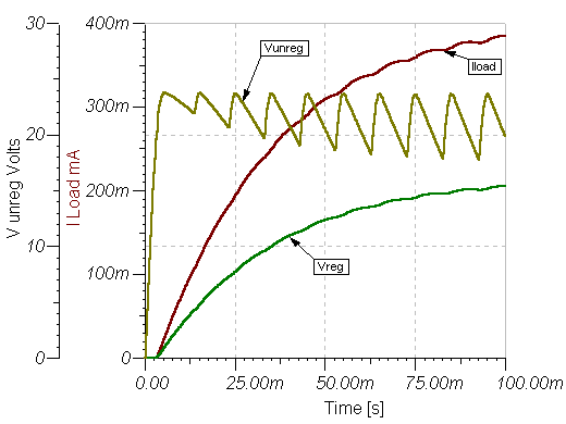
a 5000uF capacitor. The graph below shows the output
voltage and current through
the load :-

The load draws
nearly 400mA. With
the output directly from the rectifier there is about 5v pk-pk ripple
in the
output. Using the output
at the emitter of the transistor things are much better. The circuit
will
take a few hundred
milliseconds for the
output voltage to stabilize and reach maximum value. The
advantages are that a
smaller, less costly
reservoir capacitor can be used with this circuit to give a
high quality smoothed supply.
Source:www.zen22142.zen.co.uk


