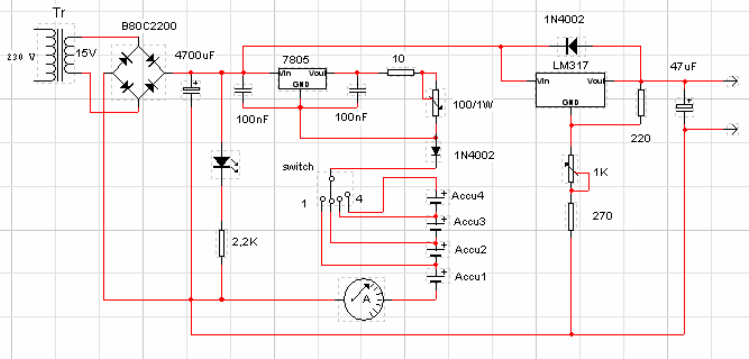
Batteries charger & PSU - ideal for digital cameras

This circuit was created for digital cameras. It's known the digital cameras have considerable power consumption. For example my camera Minolta E223 requires approximately 800 mA. In practice a mains power supply or high capacity NiMH accumulators (batteries) can satisfy this demand.
This circuit consists of two parts, charger and adapter. The
transformer, rectifier bridge and buffer condensator are
common. Adapter is quite simply its main part is an adjustable
voltage regulator LM 317 according to usual setting. Output is
a suitable for camera jack plug. Voltage can be adjusted in
range 2-9 V.
In the charger circuit a 7805 fixed voltage regulator works as
current generator assured constant current during charging.
This charging current can be adjusted with the 100 /1W
potentiometer in range about 50-300 mA indicated by a small
current measuring instrument. From one to four batteries can be
charged simultaneously. The switch must be set according to
number of batteries, and charging current of batteries given by
manufacturer must be adjusted. This circuit doesn't measure
charging time and charging condition of batteries. Manufacturers
give charging time, usually 14-16 h. I solved this problem
with a simply, cheap mechanical mains timer. I think its
accuracy is sufficient.
Sandor Dobany from Hungary
dsandor@minimail.hu


