Voltage InverterII
Source:
http://www.aaroncake.net/
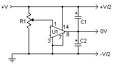
This simple and inexpensive circuit can produce a dual (positive and
negative) voltage from a single supply input. It is therefore extremely useful
for powering opamp and other circuits that require a dual voltage from a single
battery. The circuit will operate at an input voltage from around 5V to 20V and
produce a output from +-2.5V to +-10V.
Schematic
Parts
|
Part |
Total Qty. |
Description |
Substitutions |
|
R1 |
1 |
1M Linear Pot |
|
|
C1,C2 |
2 |
15uf 25V Electrolytic Capacitor |
|
|
U1 |
1 |
LM380 Audio Amp Chip |
|
|
MISC |
1 |
Heatsink For U1, Binding Posts (For Input/Output), Wire, Board |
Notes
1. U1 dissipates around 1W and will therefore require a heatsink.
2. R1 is used to equalize the outputs. The first time you use the circuit, it should be set to mid range and then adjusted with the aid of a voltmeter. Measure each output while adjusting. The circuit is calibrated when both outputs read the same voltage (either positive or negative).


