


Glitch detector
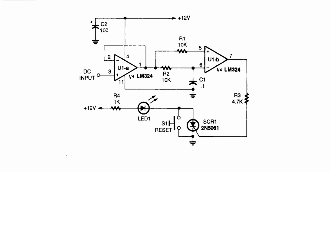
In the circuit, two op amps (half of an LM324 quad op amp) and an SCR are direct coupled in a de-voltage monitoring circuit. Op-amp U1-a is configured as a voltage follower, which feeds the bridged inputs of the second op amp, Ul-b. A resistor/capacitor combination (R2/C1) connected to the negative input of U1-b forms an RC time-delay circuit. As long as there is no change in the de-voltage level at either of U1-b's inputs, its output is near zero. If a voltage glitch occurs, the RC timing circuit will delay the voltage change at the op amp's inverting input, causing its output to go high, triggering SCR1 and causing LED1 to light. The circuit's sensitivity allows it to detect voltage changes in the millivolt range. Pressing S1 diverts the SCR's holding current to ground, causing it to turn off and reset the circuit.
Source:www.circuitos.cl.tripod.com