


Stereo Test Tone Generator
Stereo Test Tone Generator
(C) G. Forrest Cook May 5, 2003
Introduction
The purpose of this circuit is to create a pair of sine waves for testing stereo equipment. While it is useful for many types of audio test tone generation, the circuit is specialized for the purpose of aligning an FM Stereo Modulator, like the type used in low power FM stereo transmitters. Two tone outputs are available, the low tone has a secondary output that is 180 degrees out of phase with the primary output. The circuit is also handy for testing computer sound card inputs
.Specifications
Operating Voltage: 12V DC (should work ok on 9V)
Operating Current: 15ma max.
Low Output Frequency: approximately 600 Hz
High Output Frequency: approximately 800 Hz
Output Levels: approximately 0.5V - 5V P-P
Theory
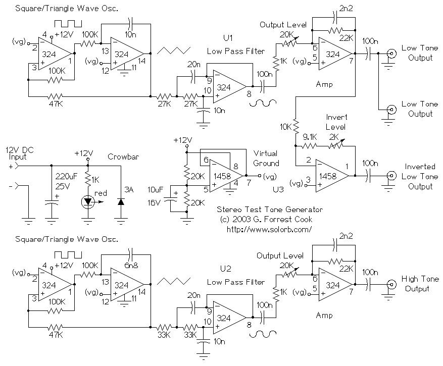
IC U3B is wired to produce a virtual ground at half of the power supply rails (6V). This is used elsewhere in the circuit as a reference. The power supply is filtered with the 220uF capacitor. The 3A diode offers some protection against reverse polarity on the power inputs. For full protection, place a 1A or smaller fuse in series with the +12V input.
The circuit has two nearly identical stereo sine wave generator circuits. U1 is the heart of the low tone oscillator, U2 is the heart of the high tone oscillator. The two op-amps on the left of each oscillator chain produce square and triangle waveforms at fixed frequencies. The frequency is set with the 10n and 6n8 capacitors.
The triangle waves are passed into low-pass filters, which remove most of the harmonic energy and produce relatively pure sine waves. The two 27K and two 33K resistors set the low pass frequency.
The sine waves are each fed into an output amplifier which can be adjusted for fixed level outputs. The low tone output is also fed into IC U3A which produces an inverted copy of the low tone signal.
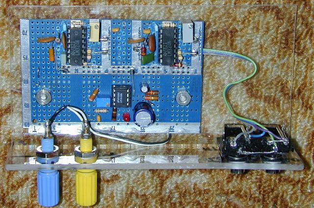
Construction
The circuit was built on a piece of perforated prototyping circuit board.. Wiring was done by hand using bare tinned copper wire covered with small pieces of teflon insulation. The circuit board and connectors were mounted on a piece of bent plastic.
Alignment
Connect an oscilloscope to the low tone output and adjust the low tone output level for a specified level, I used 4V peak-to-peak.
Connect the oscilloscope to the high tone output and adjust the high tone output level to the same level as the low tone oscillator.
Connect the oscilloscope to the inverted low tone output and adjust the invert level for the same level as the low tone output. If you have a two channel oscilloscope, connect one channel to the low tone output, connect the other channel to the inverted low tone output. Set the scope to add the channels with one of the channels inverted, then adjust the invert level control for the best null.
The circuit is not particularly stable over a wide range of temperatures. If you are using it for precision level setting, align it prior to each use. For most audio work, the alignment only needs performing one time. For the best stability, use high quality capacitors for the oscillator and filter sections.
Use
There are three stereo signal combinations that can be generated with this circuit. For a mono test signal, connect both channels to the two low tone outputs. For a stereo two tone test signal, connect one channel to the low tone output and the other channel to the high tone output. For a two phase test signal, connect one channel to the low tone output and the other channel to the inverted low tone output.
Source:www.solorb.com