


Pulse Reading Logic Probe
(C) G. Forrest Cook January 21, 2002
Introduction
This circuit uses LEDs to display logic states for high, low, rising pulse, and falling pulse, it is generally useful for debugging logic circuitry.
Specifications
This circuit can monitor TTL logic levels. TTL compatible CMOS logic families can also be monitored.
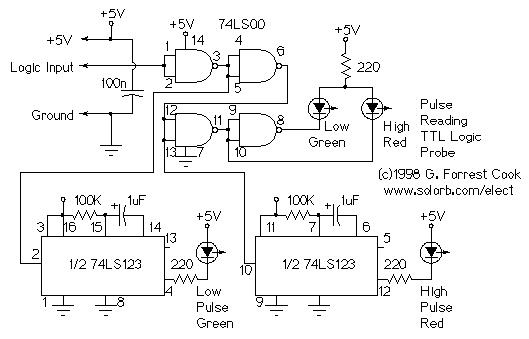
Theory
The first 74LS00 gate acts as a buffer for the input logic pin. The following gates invert the signal, then further buffer it for driving the High and Low LEDs.
The first 74LS123 one shot stretches out low going pulses so that they blink the Low Pulse LED for a long enough time to be visible. The second 74LS123 does the same thing for high going pulses.
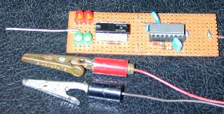
Construction
This circuit can be built on perforated circuit board and wired by hand. The completed circuit can be assembled into a clear plastic box with the wires protruding out one end. The LEDs should be visible through the box. IC sockets should be used for easy chip replacement.
Alignment
None required.
Use
Clip the probe's ground and +5V lead to the ground and +5V rails on the logic circut under test. Connect the probe lead to the logic lines that you wish to examine.
The High and Low LED indicators indicate high and low logic levels. A single high pulse will cause the High Pulse LED to light, and A single low pulse will cause the Low Pulse LED to light. A square wave or repeating pulse waveform will cause both the High and Low Pulse LEDs to light.
Source:www.solorb.com