


Ultra Low Power LCD Indicator
Low Power LCD Indicator
(C) G. Forrest Cook August 28, 2003
Introduction
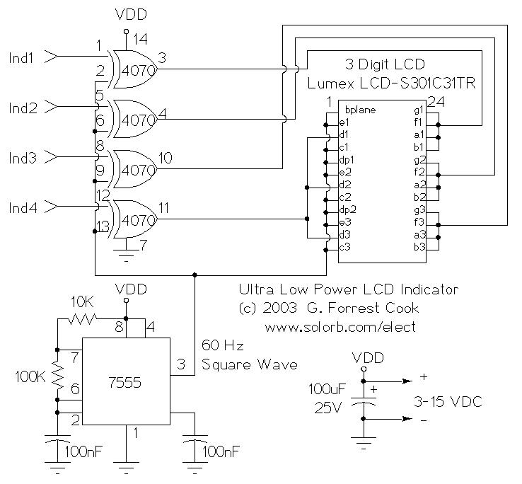
This circuit serves as an ultra-low power replacement for multiple LED on-off indicators. It also has the advantage of being easy to read in full daylight. With the parts shown, it is possible to display four bits of information.
The display that I used has three digits and 2 decimal points for a total of 23 segments. Different groupings of segments can be used for the four indicators. I chose to use three squares (shown) and the three lower segments together (not shown) for the four indicators. Many other combinations could be used, one possibility would be to hard-wire numbers or letters out of each of the digits. Other LCD displays could also be used for different effects.
A part that doesn't exist as far as I know, but should, is a single pixel LCD indicator (2 wire). An LCD manufacturer could probably make a lot of money with such a part. If such a thing exists, I'd love to hear about it.
Specifications
Operating Voltage: 3-15V (5V Nominal) DC
Operating Current: 250 microamps to 1 milliamp (400 microamps at 5V)
Operating Frequency: approximately 60 Hz
Theory
The 7555 IC (CMOS 555 timer) generates a square wave clock signal at approximately 60 hz. This signal is sent to the LCD backplane and the inputs of the four CMOS 4070 XOR gates. If the other input (ind*) of an XOR gate is low, the gate's output is a square wave that is in phase with the clock signal. If the ind* input is high, the gate's output is out of phase with the clock.
Sending a signal to an LCD segment that is in phase with the backplane signal causes the display to stay blank. Sending an out of phase signal to the LCD segment causes an AC waveform to be applied to the segment which turns it black. Multiple segments are wired in parallel to generate the desired display patterns. The LCD segments require a tiny amount of current to operate, the CMOS gates also take very little power, hence the efficient nature of the circuit. It is necessary to tie the unused segments to the LCD backplane, otherwise they may partially turn on.
If more dislay bits are needed, additional XOR gates can be connected in the same manner. Up to 23 XOR gates could be used to drive the entire display, but a microprocessor and driver software would probably be easier to put together. By generating all of the signals with a microprocessor, all of the driving circuitry can be eliminated.
Other logic families could be used to make this circuit, it should work with a standard 555 timer chip and a 74LS86 XOR gate (different pinout), for example.
Some LCDs may not operate at very cold temperatures, an engineer at Lumex said that their components will work from -30C to +75C.
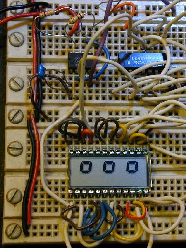
Construction
The circuit was built on a standard prototyping plug board. All of the parts can be purchased for under ten dollars.
Use
The four inputs of the CMOS 4070 IC can connect to outputs on a microprocessor, or any other logic output that needs monitoring. The supply voltage of this circuit should be the same as the driving logic's supply voltage.
Parts
1X Lumex LCD-S301C31TR 3 digit LCD display (from Digi-Key), or equivalent
1X CMOS 4070 quad XOR Gate, a CMOS 4030 should also work.
1X 7555 CMOS 555 timer chip
2X 100nF capacitor
1X 100uF 25V electrolytic capacitor
1X 10K 1/4W resistor
1X 100K 1/4W resistor
Source:www.solorb.com