Multi Wire Cable Tester
Circuit : Andy CollinsonEmail: anc@mitedu.freeserve.co.uk
Description:
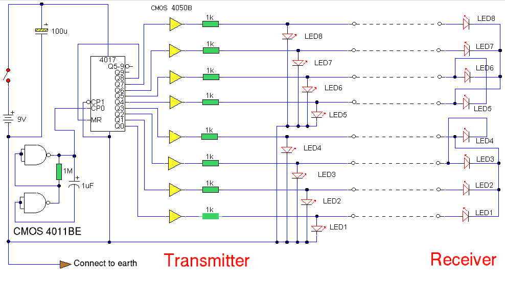
A multi wire cable tester with a separate LED for each wire. Will show open circuits, short circuits, reversals, earth faults, continuity and all with four IC's. Designed initially for my intercom, but can be used with alarm wiring, CAT 5 cables and more.
Full circuit can be viewed with resolution of 1024x768


Circuit Notes:
Please note that for clarity this circuit has been drawn without showing power supplies to the CMOS 4011 and CMOS 4050 IC's. The positive battery terminal connects to Pin 14 of each IC and negative to Pin 7. The CMOS 4017 uses Pin 16 and Pin 8 respectively. Note also that as the CMOS 4050 is only a hex buffer, you need 8 gates so two 4050's are required, the unused inputs are connected to ground (battery negative terminal).
Circuit Description:
The circuit comprises transmitter and receiver, the cable under test linking the two. The transmitter is nothing more than a "LED chaser" the 4011 IC is wired as astable and clocks a 4017 decade counter divider. The 4017 is arranged so that on the 9th pulse, the count is reset. Each LED will light sequentially from LED 1 to LED 8 then back to LED 1 etc. As the 4017 has limited driving capabilities, then each output is buffered by a 4050. This provides sufficient current boost for long cables and the transmitter and receiver LED's. The receiver is simply 8 LED's with a common wire...read on.
Wiring the CMOS 4017
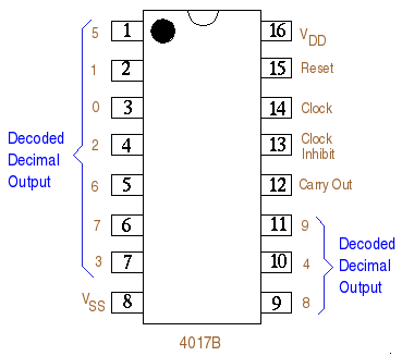
The pinout for the CMOS 4017B is shown below. Please note that in the main schematic above, alternate naming of the pins has been used. The pin eqivalence is as follows:-

CP0 (clock pulse zero) is the Clock input, Pin 14 on the diagram above.
CP1 (clock pulse one) is the clock inhibit or Pin 13 on the pinout above.
MR (master reset) is the reset pin 15 in the diagram above.
Q0-9 represent the decoded decimal outputs. Hence Q0 is Pin 3 on the pinout and Q8 is Pin9.
Not a mistype. The problem with testing each wire individually is that if you had 7 individually addressable LED's, then you would need an eight return or common wire. In the case of testing 8 wires you would need a ninth wire. You could use a domestic earth but its not really practical, and also if the cable was shorting to earth anyway it would be no good anyway. The solution had me thinking for a while, but since this is a logic circuit, there are only two conditions, logic high or zero. As the 4017 outputs are either high or low, any output can provide a common return path for a LED. So LED's 1 - 3 use the 4th output of the 4017, which will be zero, and the 4th LED is wired with reverse polarity. On the 4th pulse, output 4 is high, output 3 is low and so the LED will light. If the common return wire is open circuit then LEDs 1-4 will not light. A similar situation occurs with outputs 5 to 8. The common wire in can be taken from any output terminal from the 4017, but the same rule would still apply. The ability to test all wires quickly outweighs this small disadvantage. If a cable of just 4 or 6 wires is tested then it must use the wires with LED's numbered 1 to 4 or 1 to 6, which is why the LED's are numbered that way.
Testing:
With a good cable and all wires connected then LED 1 will light at both cable ends, followed in sequence by LED 2 ,3, 4 etc to LED 8, the sequence then repeating. If a 4 wire cable is used, it must be connected to use the common return wire as described in the preceeding paragraph. The sequence would be LED 1,2,3,4 repeating with a delay as the 4 unused outputs are stepped through.
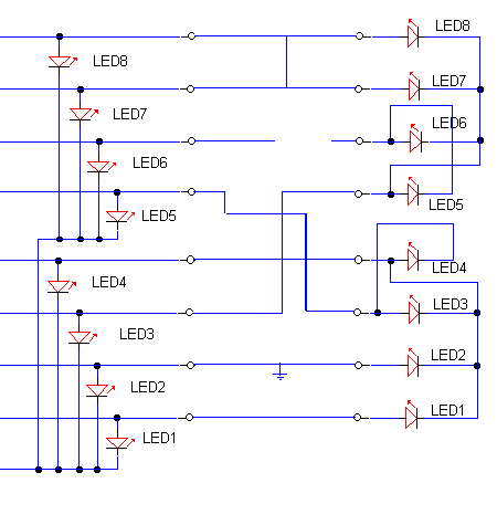
To check for earth contact faults, the probe labeled "to earth connection" would be physically connected to a local earth. A wire that is earthing will dim or extinguish the LED's at both ends of the cable. An LED not lighting at the receiver, indicates a broken or open circuit. If two wires are short circuit, example 3 and 4 then at the receiver the sequence would be 1, 2, 34, 43, 5, 6, 7, 8. A reversal would be indicated by an out of pattern sequence of LED's. Here's an example, the probe is connected to an earth at the transmitter, the cable is very faulty, wire 1 is OK, 2 is earthing, 3 and 5 are reversed 4 is OK, 6 is open circuit and 7 and 8 are short circuit. See below.

Test Result for Above Faulty Cable:
The transmitter pattern:                         The receiver pattern would be:
            1 ON                                             1 ON
            2 OFF or Faint                                   2 OFF or faint
            3 ON                                             3 (would show LED 5)
            4 ON                                             4 ON
            5 ON                                             5 (would show LED 3)
            6 ON                                             6 OFF
            7 ON                                             7 (would show 7 & 8)
            8 ON                                             8 (would show 7 & 8)
The LED sequence of course is stepped through, as you know the transmitter "pattern" it is easy to tell the state of the cable
by viewing the receiver pattern. The earth condition will only show up if the contact to earth is less than 1000 ohms, a better
but more time consuming method foe earth faults is to use a meter on the Megaohms range.Source:www.zen22142.zen.co.uk


