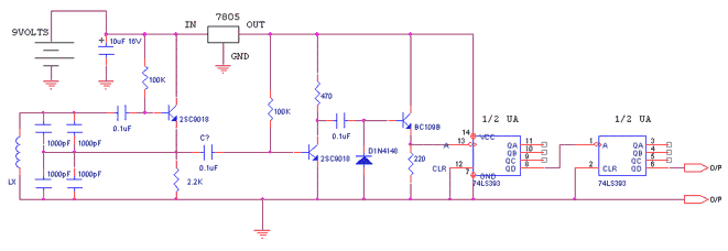
Inductive meter adapter
The following circuit enables me to measure inductance of the
inductor labeled LX which is the inductance to be measured. The
o/p of the circuit is a TTL square wave whose frequency relates to
the inductance being measured.
The inductance meter adapter output is connected to a frequency
meter and the inductance is calculated from the frequency. Hence
you need a frequency meter and some calculation to get your
inductor value.
HOW IT WORKS
The heart of the circuit is the buffer colpitts oscillator(the
first stage) which resonates with the unknown inductance to give a
Sine wave of a particular frequency . The frequency of the sine
wave is a function of the unknown inductance and the four 1000pF
capacitors. The output sine wave is amplified by the second
transistor and is then rectified by the capacitor and diode
combination that follows. The rectified sine wave now having only
positive excursions is buffered by the third transistor and is
then fed to the 74ls393 Counter ic which is configured as a
divide by 256 counter. The output of the ic pin 6 and ground is
connected to the frequency meter.
NOTES
The 7805 regulator powers the IC and the last 2 transistors
The circuit operates from a 9V battery which also feeds the
regulator
The Ic consists of two counters in one package of 14 pins hence
you need just one.
PIN 14 is VCC and PIN 7 is ground
The ic is TTl IC
PERFORMANCE AND GETTING YOUR READING
My own digital meter can read frequency so I use it to take the
reading.
I programmed my calculator to get me the inductance value from the
reading. A simple computer programme can do this as well.
Actual frequency= Read frequency*256
Actual frequency=1/(2**(Lx(uH)*1000e-12))
So the last equation allows you to solve for the value of the
inductance Lx which will be in microhenries.
ADDITIONAL COMMENTS
This inductance measuring scheme works well for inductances of
even low values less than 1uH. However the lower
Values could have error due to the circuit including test lead
inductance. The circuit is that sensitive. I play with some tricks
to get around this which I will discuss later if people are
interested in the circuit. I wish it was a stand alone unit but
here in my country NIGERIA(IN WEST AFRICA) and my city Ibadan
there are no fancy PICS or Digital displays to make it a stand
alone unit so I just have to make do with Simple IC’S and
transistors.
Sorry the equations don’t look too neat I hope you get them
though.
Any comments about this circuit can be mailed to me and I hope
somebody finds it interesting enough to construct
And possibly make a stand alone unit with microprocessors or PICS
and displays that I haven’t got.
All resistances are in ohms
7805 positive regulator 5v o/p
2SC9018 is a high frequency transistor with FT of 1.1 Ghz . you
need high frequency transistors in the circuit where it is used in
case you want to substitute for it. I guess 2n2857, 2n5179 ,BF180
can be substituted
By Tosin Osanyintuyi (TAFRICA)
tosinopro@yahoo.com


