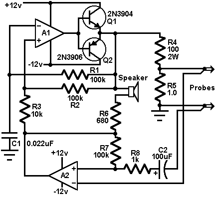
Beeper to find short circuits

This circuit uses two 741s or equivalent op amp to form a beeper that is used to detect short circuits. This design offers a way to trace resistance in the milliohm range, right to a short between bridged traces beneath a solder mask. A1 is configured as a multivibrator. R1 and C1 determine the frequency of oscillation and Q1 and Q2 boost the output. Assuming a virtual ground at the output of A2, free-run frequency is about 1kHz. Q1 and Q2 deliver a +/-10v squarewave to R4, dumping a +/-100mA through a short circuit placed across the probe tips. R5 ensures that the open circuit voltage never exceeds +/-0.1v. A2 monitors the voltage between the probes. When the probes are open, A2's gain equals the R4/R5 divider loss, and the output of both amplifiers is identical. This has two effects: First, hysteresis is greatly increased and frequency falls to a low growl, and secondly, the loudspeaker that bridges the two in-phase outputs is effectively silenced. A dead short across the probe tips will return nothing to A2 and the circuit will squeal at its nominal 1kHz rate. Anything less than a perfect short produces some output from A2, increasing multivibrator hysteresis and lowering the pitch.


