60 LED Clock
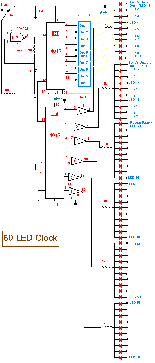
This months project is based on the 4017 chip that we used in a project last month. If you haven't had a chance to review the basics of the 4017 chip you may want to review the info presented in June's project of the month.
As you can see see we have changed the circuit a little. For example, the 4093 NAND gate is now set to exactly 1 second clock pulses. The clock rate is determined by the resistor and capacitor combination on the 4093. If the resistor is 220k ohms and the capacitor is 4.7uf then the output will be 1 second clock pulses. To increase the clock rate you should decrease the value of the resistor or capacitor. To decrease the clock rate you should increase the value of the resistor or capacitor. Please remember to ground all unused legs of the 4093 or noise in the circuit will occur and cause the clock to malfunction. Therefore, ground pins 5,6,8,9,12, and 13. To operate the circuit simply move the switch from STOP to RUN.

Source:www.home.maine.rr.com


