


Assortment of Siren Circuits
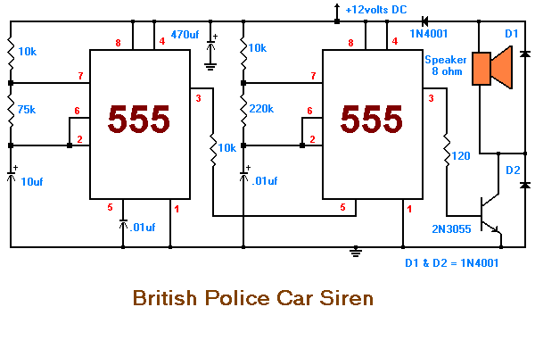
This month I am making 3 different types of siren circuits based on the 555 timer. The first circuit simulates the siren of a British police car. It uses two 555 timers in the circuit. The 555 on the right is wired as an alarm tone generator and the second 555 timer on the left is a 1 Hz astable multivibrater. The output of the left timer is to frequency modulate the right timer. This causes the right timers frequency to alternate between 440Hz and 550Hz at a 1 Hz cyclic rate. The transistor is used to help strengthen the signal to the speaker.
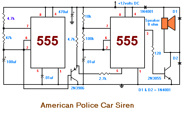
The second circuit simulates the siren of an American police car. It uses two 555 timers in the circuit. The 555 on the right is wired as an alarm tone generator and the second 555 timer on the left is wired as a low frequency astable timer which generates a ramp waveform of about 6 seconds that is buffered by the transistor and again used to frequency modulate the tone generator. The transistor is used to help strengthen the signal to the speaker.
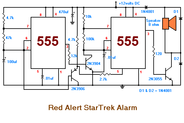
The third circuit simulates the "Red Alert" siren from the TV show Star Trek. It uses two 555 timers in the circuit. The 555 on the right is wired as an alarm tone generator and the second 555 timer on the left is wired as a 1.5 second non-symmetrical astable that generates a fast rising but slow falling saw tooth waveform. This waveform is buffered by the transistor and used to frequency modulate the tone generator and making its frequency rise slowly during the falling parts of the saw tooth but collapse rapidly during the rising part of the saw tooth. The output starts as a low frequency, rises for 1.15 seconds to a high tone, ceases for .35 seconds and then repeats the cycle.
Source:www.home.maine.rr.com