


Single Zone CMOS Alarm
Circuit :Ron JEmail Ron
Description:
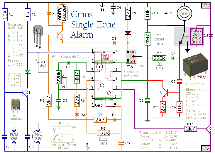
This circuit features automatic Exit/Entry delays, timed Bell Cut-off and System Reset. It has provision for normally open and normally closed switches and will accommodate the usual input devices such as Foil Tape, Pressure Mats, Magnetic Reed Contacts, Passive Infrared Detectors and Inertia (Shock) Sensors.
Notes:
The green Led should be lighting before you set the alarm. When you open SW1 The red Led will light and the Exit delay will begin. You have about 30 to 40 seconds to leave the building. As you do so the buzzer will sound. It should stop sounding when you close the door behind you; indicating that the trigger circuit has been successfully restored within the time allowed. On returning, when you open the door the buzzer will sound again. You then have about 30 to 40 seconds to move SW1 to the "off" position. If you fail to do so, the siren will sound. After about 15 to 20 minutes, when the relay drops out, the alarm will attempt a Reset by using Q3 to switch itself "off" briefly. If the trigger circuit has been restored the alarm will reset. If not, the attempt will fail and the alarm will reactivate. It will go on trying to reset itself every 15 to 20 minutes until the trigger circuits are restored; or the alarm is switched off.
The Exit delay, Entry delay and Bell Cut-off times may be changed by altering the values of R12, R8 & R11 respectively. The sensitivity of the Inertia Sensors is adjusted by R4. Set to minimum value, a light tap will activate the alarm. Set to maximum value, a heavy blow is required. If you are not using Inertia Sensors then replace R4 with a 220k fixed resistor. If you are not using normally open switches then leave out R1, C1 & Q1 and fit a link between the green Led and C2.
Construction:
The terminals are a good set of reference points. To fit them you'll need to enlarge the holes to 1.3mm. Now turn the board over and cut the tracks in the 34 places shown. Make sure that the copper is cut all the way through. Sometimes a small strand of copper remains at the side of the cut and this will cause malfunction. If you don't have the proper track-cutting tool, then a 6 to 8mm drill-bit will do. Just use the drill-bit as a hand tool; there is no need for a drilling machine.
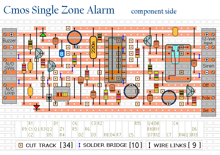
Next fit the 9 wire links. I used bare copper wire on the component side of the board. Telephone cable is suitable; the single stranded variety used indoors to wire telephone sockets. Stretching the core slightly will straighten it; and also allow the insulation to slip off.

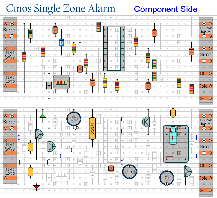
The next stage is to fit the resistors, most of the diodes, and the IC socket. Using a socket reduces the chances of damaging the IC; and makes it easier to replace if necessary. The resistors are all shown lying flat on the board. However, those connected between close or adjacent tracks are mounted standing upright; as are some of the diodes.
Finally, fit the remaining components (capacitors, transistors, diodes and relay); add the 10 solder bridges to the underside of the board; and finish off by inserting the Cmos 4081 into the socket.
The Support Material for this alarm includes a parts list, a detailed circuit description and more.
Source:www.zen22142.zen.co.uk