Single Zone Alarm
Circuit :Ron JEmail Ron
Description:
A single zone alarm circuit with entry and exit delay and other facilities.

Notes:
The circuit features automatic exit and entry delays, timed bell cut-off and system reset. It has provision for normally open and normally closed switches and will suit the usual input devices (Pressure Mats, Magnetic Reed contacts, Foil Tape, PIRs and Inertia Sensors). When the power is applied, if there's a fault the buzzer will sound and you should switch off again and check for open doors, windows, etc. If everything is in order the buzzer will NOT sound and the exit delay will begin. You have about 30 seconds to leave the building. When you return the buzzer will sound. You then have about 30 seconds to switch off; otherwise the siren will sound. It will go on sounding indefinitely. However, if the building is re-secured the siren will switch off after about 10 minutes and the alarm will reset.
The Exit delay, Entry delay and Bell Cut-off times can be changed by altering the values of R4, R12 & R13 respectively. Q5 and Q6 ensure that the Entry delay and Bell cut-off timers always start with C7 either fully charged or fully discharged as required. If you can live with slightly less precise time intervals then leave out Q5, Q6, R14, R15, R16, R17, C8 & C9. If you don't want a Bell Cut-off at all then leave out D3 as well.
The sensitivity of the Inertia Sensors is adjusted by R8. Set to minimum value, a light tap will activate the alarm. Set to maximum value, a heavy blow is required. If you are not using Inertia Sensors then replace R8 with a 27k fixed resistor. If you are not using normally open switches then leave out R1, C1 & Q1 and fit a link between R2 and C2.
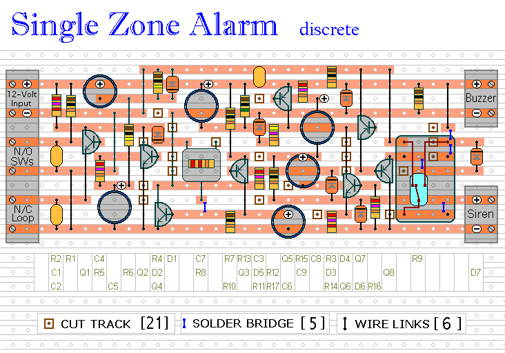
Veroboard Layout:

The Support material for this alarm includes a step-by-step guide to the construction of the circuit-board, a parts list, a detailed circuit description and more.
Source:www.zen22142.zen.co.uk


