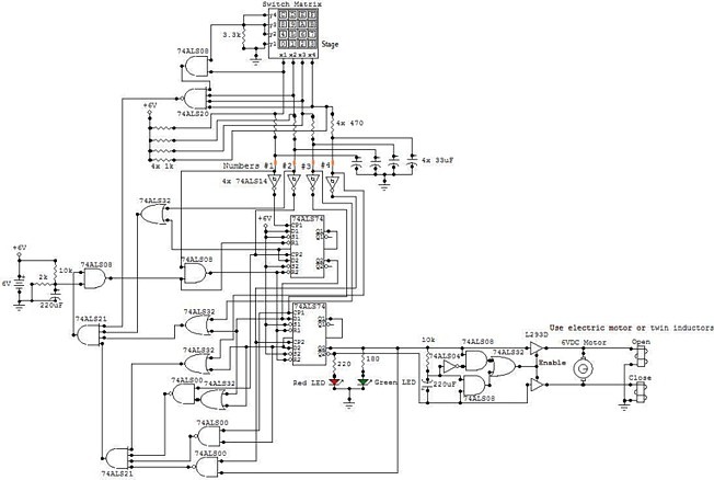
Electronic Locker
This circuit is an Electronic Locker. It is
controlled by a switches combination (by a code). There is
a switch matrix on the door of the locker. This one is a
unit of switches connected into 4 arranged of 4 columns for
a total of eight terminals. When we press on a switch, this
one establishes the contact between its column and its
line. This switch matrix is also used in the telephones,
for example. But it is numbered from 0 to 9 and from A to F
for a total of 16 switches. To open the locker, we have to
press 4 specific and different switches in the good order.
If for example the code is 0,1,2,3 and we press two times
to the same switches: 0,1,2,2,3 the locker won't open. In
this circuit, the code is 0,1,2,3 but we can set the
desired code when we built de circuit. The desired line
(called "stage" in the schematic) is connected to the
ground and to a pin of the 3.3k resistor and the other line
is connected to an input of the 7408 and to the other pin
of the resistor.
All the desired numbers of the code are in
the same line. To set the order of the number of the code,
we have to set the good connection between the node of the
7414 input and the appropriate node of the capacitor. For
example, if we select the first line (y1) and the code is
0,1,2,3 the first number (#1) is connected to the top left
contact (x1). The switch 0 is corresponding to x1/y1. These
points of contact are colored in orange in the schematic.
When the locker is locked, the red LED is turned on and the
green LED is turned off. When the locker is opened, the red
LED is turned off and the green LED is turned on. To lock
the locker, we can push any of the 16 switches of the
matrix. The locker is powered by a 6V source. I recommend
using a 6V rechargeable battery because this one lasts a
long time (at least 3 full days) and can be re-used.
Otherwise, we can use four 1.5V battery connected in
serial. These least only 5 hours but are less expensive.
To save energy, we can remove the red LED. When the locker is powered on, it is locked. The electric motor or the inductors close the door while a bit of time and after, stop working. When we open the locker, the electric motor or the inductors open the door while a bit of time and after, stop working. To control the state of the door (open or lock) we can use an electric motor or a pair of inductors. If we use a electric motor, when the locker is closed, the motor turns in the anti-clockwise direction during a certain time and moves down a toothed bar. After this time, the motor stops turning and the locker remains closed. When the locker is opened, the motor turns in the clockwise direction during a certain time and moves up the toothed bar.
After this time, the motor stops turning and the locker remains opened. If we use two inductors, when the locker is closed, the second inductor works during a certain time and moves left a magnetic bar by attraction. After this time, the inductor stops working and the locker remains closed. When the locker is opened, the first inductor works during a certain time and moves right the magnetic bar. After this time, the inductor stops turning and the locker remains opened. The buffer (L293D) who controls the motor or the inductors has two Vcc inputs and four ground connections. The both Vcc inputs must be connected to the +6V and all ground connections must be connected to the ground of the circuit. All the parts of the circuits are placed in the rack except the DELs and the switch matrix which them, are placed on the door.


