Simple Surround Sound Decoder
Introduction
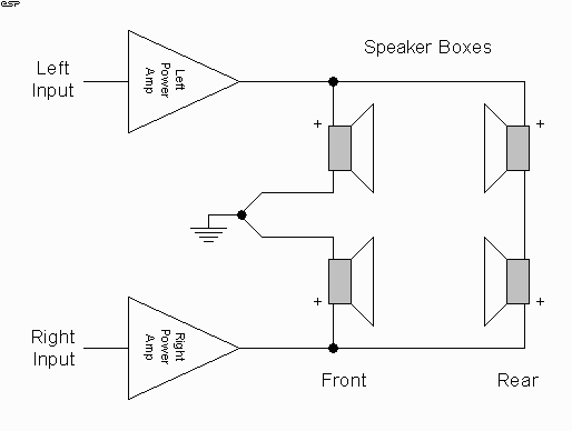
This surround-sound decoder is based on the "Hafler" principle, first discovered by David Hafler sometime in the early 1970s. The original idea was to connect a pair of speakers as shown in Figure 1, for use as the rear speakers in the surround setup.
This is ok just as it stands, but problems are created if the main speakers are bi-amped or using bridging, for example, since there is no longer a full-range / full power signal available for the rear speakers. There is also no way to control the level reproduced, since it will always simply be the difference signal between left and right channels.
If the signal is mono, then the signal in both channels will always be more or less identical, and there will be no output from the rear speakers at all.

Figure 1 - The Original "Hafler"
Surround-Sound Matrix
This circuit works by allowing the rear speakers to reproduce only the difference signal between the left and right outputs. All stereo encoded material has some difference between left and right channels (if it didn't, it would be mono), and it is this difference signal that is reproduced by the rear speakers.
It is important to ensure that the connection between the rear speaker negative terminals is not earthed, or they will simply be in parallel with the main speakers.
Line Level Passive Version
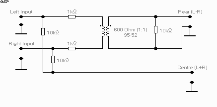
So, if you want to use separate amps for the rear speakers, basically you can't - unless you get sneaky. The first circuit in Figure 2 is completely passive, but requires that a suitable transformer is available. A suitable transformer means a line level, 10k impedance unit with a 1:1 ratio - these are very scarce (I would suggest almost impossible to get).
You might be able to get away with a 600 Ohm unit, but because of the impedances you need, its performance will be very ordinary, with an extreme lack of bass (there is not enough inductance for a 600 Ohm transformer to work satisfactorily at high impedances). Loading the transformer will give back some of the bass, but the preamp is unlikely to be very happy with the resulting impedance.

Figure 2 - A Passive Line Level Hafler Matrix
Decoder
The circuit shown is not a bad compromise, although the impedances are too low for anything other than a solid state preamp (preferably using opamps). Using a telephony transformer (600 Ohm), the loss overall is about 3dB, with a low frequency -3dB point around 100Hz. This will vary depending on the quality of the transformer used, so experimentation will be needed. Although 600 Ohm telephony transformers are reasonably readily available, many of them are pretty nasty (actually, disgusting is probably closer).
My tests were on a really good one, built by an Australian company called Transcap. I think I can say with some certainty they will be rather unwilling to sell one-off quantities. Another manufacturer of really nice transformers is Midcom in the US, but you will have the same problem with them. These manufacturers are set up to deal with large orders from other companies, not the likes of you and me wanting one ("You want ... ONE ??") transformer. As a result you will have to take whatever you can get.
Since it is unlikely that this will be viable for most constructors, the alternative is to go active, using a dual opamp to perform the functions. This is described next.
The New Circuit
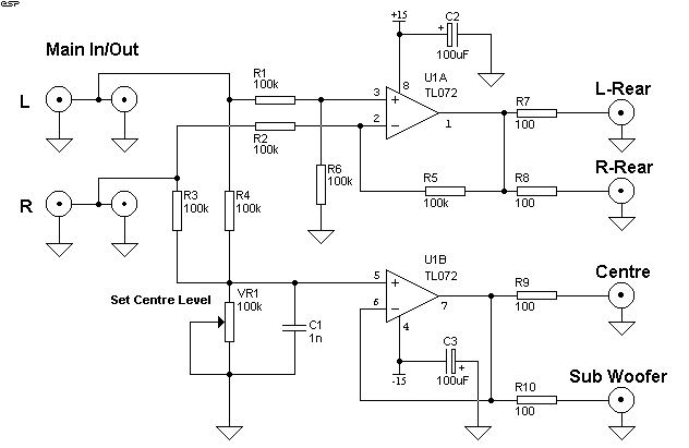
The schematic shown in Figure 2 is a simple way to achieve the same thing (with some additional benefits) at line level (i.e. before the signal reaches the power amplifiers - in a bi-amped system, this circuit must be between the preamp and the electronic crossover). The extras available are readily apparent:
- Wiring is simplified (although additional power amplifiers are needed)
- We now have a centre channel signal available
- Provision for a mono signal to a sub-woofer is easy

Figure 3 - The Schematic of an Enhanced Hafler
Matrix Decoder
Although there have been similar circuits published over the years, this is a little different in a few areas. I wanted to avoid having any active electronics in the main Left and Right channels, since this eliminates any possibility of sound degradation due to the introduction of the opamps. The input impedance of 50k will not pose a problem for any preamp (including valve types), and the main signal is simply in parallel with the additional circuitry.
No volume control has been included, since you already have one in the preamp. It would just become another component to fiddle with, and since it would be rarely used, would probably become noisy over time.
How It Works
Opamp U1A is connected as a subtracting amplifier. Should the
same signal be applied to both inputs, the output is zero. As a result, it will remove all
common information from the stereo signal, and reproduce only the difference signal - in
exactly the same way as the original Hafler design.
U1B is a simple summing amplifier, and the output contains all the information from both the left and right channels. A possibility that springs to mind is that we could then subtract the difference information from this output, so that only material that is absolutely common to both channels would be reproduced. Would this improve the performance to the extent that the extra circuitry is warranted? I tend to doubt it, but will look into this further.
Centre Channel Control
The pot (VR1) is to set the centre channel level. This can be
a trimpot, or a conventional pot mounted at the rear (to help prevent "fiddlers"
from mucking up the settings you like). I have seen circuits which do not include
this, which seems basically a bad idea. When the two channels are summed, the centre
channel will typically have a level of -3dB relative to the left and right channels -
provided the signal is not mono. Centre channel speech (for example) will be mono, so the
level will be equal to that of each of the main speakers. Since the centre channel amp and
speakers are rarely as powerful as the main Left and Right channels, there is a distinct
possibility of overload of the amp, the speaker or both.
Since the centre channel is supposed only to fill the "hole" and provide a stable centre sound image, it does not need to be as loud - especially since it will almost certainly have inferior sound quality to the main speakers and will therefore degrade the overall sound quality. The level control will allow you to set the level to just sufficient to provide the stable sound image, and no more.
The capacitor (C1) is optional. It provides a nominal 8kHz roll-off frequency (which is apparently quite normal for "real" surround-sound processors). This helps to minimise any disturbance to the main stereo signal, but feel free to leave it out, since most centre channel speakers probably won't be able to reproduce much above this frequency anyway.
Sub-Woofer Output
The sub-woofer output is simply taken directly from the
centre channel mixer, and I included no low-pass filter because I don't know of any sub
which does not have a filter already. Adding another one simply adds unnecessary
complexity, and will introduce phase shift at the output that a phase compensation circuit
(often included in sub woofers) may not be able to cope with.
Miscellaneous
The 100 Ohm resistors in the outputs are to prevent the
capacitance of the signal leads causing the opamps to oscillate. At this value, they will
cause no high frequency loss, unless you insist on 100m long signal leads (in my
experience, these are uncommon).
It will also be noticed that there are two outputs for the rear speakers, simply in parallel. I included this because it is easier to wire if the user is connecting a stereo amp for the rear speakers. Naturally, a mono amp will do just fine, as long as it is capable of driving the two rear speakers in parallel. This may not be possible if the speakers are 4 Ohm types (these are becoming more common in hi-fi, so its not that silly).
Construction
The unit can be housed in any suitable metal case (it does not need to be displayed, and can hide up the back of the cabinet). A metal case is preferred to prevent any noise (especially hum) pickup from mains cables, etc. To power the unit, I suggest the power supply presented in Project 05 - this is simple, safe and cheap.
Since heat generation is not an issue, the case can be as small as you like, as long as there is enough room for the RCA connectors and other components. Be careful that you don't pack everything in the case too tightly, though, because you might create short circuits jamming everything in if it is too small.
The dual opamp and other components can be wired on a piece of Veroboard (or similar), and layout is not critical. As always, use 1% metal film resistors throughout, for minimum noise and maximum stability and reliability. It is expected that this circuit will be extremely reliable as long as care is taken when building it, so there is no need to make it so it is easily serviced. I have built similar devices in the past that have never required repair in over 20 years.
All RCA connectors can be hard wired, and since crosstalk is not likely to be a problem with this unit, the wiring is not critical. You must pay close attention to earthing - all RCA sockets and the power supply centre-tap (0Volt line) must be connected securely to the case to prevent noise pickup.
If desired, 100nF polyester caps can be connected in parallel with the 100uF supply bypass capacitors, but they are not really needed and performance will not suffer if they are omitted.
Delay Line
One thing that is missing from this simple circuit is a delay line. This is normally used to delay the sound supplied to the rear speakers, and effectively makes the sound stage larger by making the rear speakers sound further away. It also adds a degree of additional ambience, and is used in virtually all commercial surround decoders.
Unfortunately, although a delay line project was published, the IC disappeared within minutes - it is no longer made or available. A new one may (or may not) be published some time in the future.


