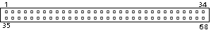
 68 pin male connector at the controller | | Pin | Namel | Host | Dir | Dev | PC-Card equiv |
|---|
| 1 | Ground | x |  | x | Ground |
| 2 | DD3 | x |  | x | D3 |
| 3 | DD4 | x | | x | D4 |
| 4 | DD5 | x | | x | D5 |
| 5 | DD6 | x | | x | D6 |
| 6 | DD7 | x | | x | D7 |
| 7 | /CS0 | x | | x | /CE1 |
| 8 | | | | i | A10 |
| 9 | /SELATA | x | | x | /OE |
| 10 | | | | | |
| 11 | /CS1 | x | | x 1) | A9 |
| 12 | | | | i | A8 |
| 13 | | | | | |
| 14 | | | | | |
| 15 | | | | i | /WE |
| 16 | INTRQ | x |  | x | /READY:IREQ |
| 17 | VCC | x | | x | VCC |
| 18 | | | | | |
| 19 | | | | | |
| 20 | | | | | |
| 21 | | | | | |
| 22 | | | | i | A7 |
| 23 | | | | i | A6 |
| 24 | | | | i | A5 |
| 25 | | | | i | A4 |
| 26 | | | | i | A3 |
| 27 | DA2 | x | | x | A2 |
| 28 | DA1 | x | | x | A1 |
| 29 | DA0 | x | | x | A0 |
| 30 | DD0 | x | | x | D0 |
| 31 | DD1 | x | | x | D1 |
| 32 | DD2 | x | | x | D2 |
| 33 | /IOCS16 | x | | x | /WP:IOIS16 |
| 34 | Ground | x | | x | Ground |
| 35 | Ground | x | | x | Ground |
| 36 | /CD1 | x | | x | /CD1 |
| 37 | DD11 | x | | x | D11 |
| 38 | DD12 | x | | x | D12 |
| 39 | DD13 | x | | x | D13 |
| 40 | DD14 | x | | x | D14 |
| 41 | DD15 | x | | x | D15 |
| 42 | /CS1 | x | | x 1) | /CE2 |
| 43 | | | | i | /VS1 |
| 44 | /DIOR | x | | x | /IORD |
| 45 | /DIOW | x | | x | /IOWR |
| 46 | | | | | |
| 47 | | | | | |
| 48 | | | | | |
| 49 | | | | | |
| 50 | | | | | |
| 51 | VCC | x | | x | VCC |
| 52 | | | | | |
| 53 | | | | | |
| 54 | | | | | |
| 55 | M/S- | x | | x 2) | |
| 56 | CSEL | x | | x 2) | |
| 57 | | | | i | /VS2 |
| 58 | /RESET | x | | x | RESET |
| 59 | IORDY | o | | x 3) | /WAIT |
| 60 | DMARQ | o | | x 3) | /INPACK |
| 61 | /DMACK | o | | o | /REG |
| 62 | /DASP | x | | x | /BVD2:SPKR |
| 63 | /PDIAG | x | | x | /BVD1:STSCHG |
| 64 | DD8 | x | | x | D8 |
| 65 | DD9 | x | | x | D9 |
| 66 | DD10 | x | | x | D10 |
| 67 | /CD2 | x | | x | /CD2 |
| 68 | Ground | x | | x | Ground |
x = Required.
i = Ignored by host in ATA mode.
o = Optional.
nothing = Not connected.
1) Device shall support only one /CS1 signal pin.
2) Device shall support either /M/S or CSEL but not both.
| 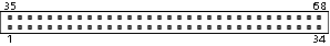 68 pin female connector at the peripherals |


