


HiJack Alarm
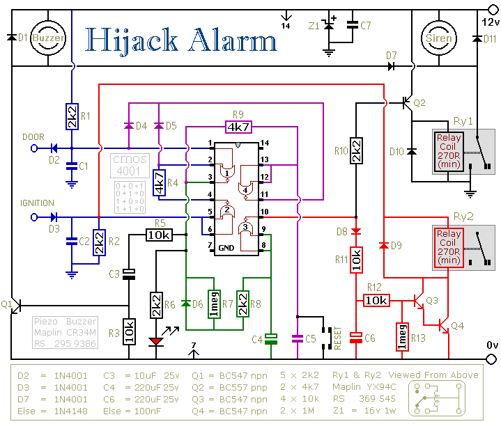
Description:This circuit is designed primarily for the situation where a hijacker forces the driver from the vehicle. If a door is opened while the ignition is switched on, the circuit will trip. After a few minutes delay - when the thief is at a safe distance - the alarm will sound and the engine will fail.
Notes:
Before fitting this or any other engine cut-out to your vehicle, carefully consider both the safety implications of its possible failure - and the legal consequences of installing a device that could cause an accident. If you decide to proceed, you will need to use the highest standards of materials and workmanship.
You're going to trip this alarm unintentionally. When you do, the LED will light and the Buzzer will give a short beep. Its length is determined by C3. Its purpose is to alert you to the need to push the reset button. When you push the button the LED will switch-off. Its purpose is to reassure you that the alarm has in fact reset.
If the reset button is not pressed then about 3 minutes later both the Siren and the Buzzer will begin to sound continuously. The length of the delay is set by R7 & C4. For extra effect, fit a second siren inside the vehicle. With enough noise going on, you may feel that it's unnecessary to fit the engine cut-out - in which case you can leave out D8, D9, R11, R12, R13, C6, Q3, Q4 & Ry2.
Even if you missed the early warning, there is still time to reset the alarm before Ry2 de-energizes and the engine fails. This additional delay - currently about 1 minute - is set by C6 and R13.
How you bring your vehicle to a standstill is up to you. It should happen when Ry2 drops-out. The contacts of Ry2 are too small to do the job themselves. Use them to switch the coil of a larger relay. Remember that the relay must be suitable for the current it's required to carry. Choose one specifically designed for automobiles - it will be protected against the elements and will give the best long-term reliability. You don't want it to let you down on a cold wet night - or worse still - in fast moving traffic!!! Fit a 1N4001 diode across its coil to prevent damage to the Cmos IC.
YOUR relay should drop-out when Ry2 de-energizes. Wire YOUR relay so that when it drops-out the engine will stop. Because turning-off the ignition will cause both Ry2 and YOUR relay to de-energize, the standby current will be low - and the engine will be disabled while the vehicle is parked.
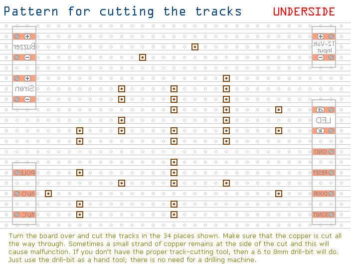
The circuit board must be protected from the elements. Dampness or condensation will cause malfunction. Fit a 1-amp in-line fuse AS CLOSE AS POSSIBLE to your power source. This is VERY IMPORTANT. The fuse is there to protect the wiring - not the components on the circuit board. Please note that I am UNABLE to help any further with either the choice of a suitable relay - or with advice on installation.
Both the Siren and the Buzzer will go on sounding until the alarm is reset. The circuit is designed to use an electronic Siren drawing up to about 500mA. It's not usually a good idea to use the vehicle's own Horn because it can be easily located and disconnected. However, if you choose to use the Horn, remember that Ry1 is too small to carry the necessary current. Connect the coil of a suitably rated relay to the "Siren" output. This can then be used to sound the Horn.
In order to reset the circuit, you must EITHER turn off the ignition OR close all of the doors before you press the reset button. While BOTH the ignition is on AND a door remains open the circuit will NOT reset.
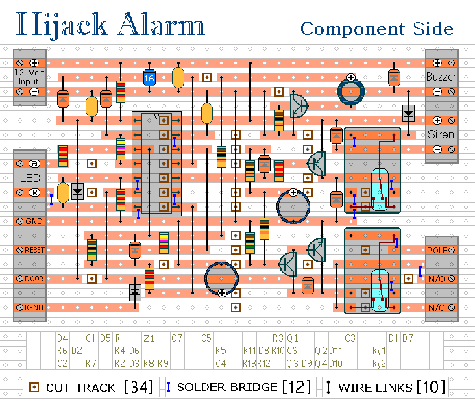
The Support material for this alarm includes a step-by-step guide to the construction of the circuit-board, a parts list, and a detailed circuit description.
Source:www.zen22142.zen.co.uk