OPAMP Theory & Design
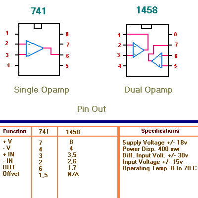
The Operational Amplifier ( Op Amp ) can be used in many different ways. The Op-amp has two inputs an inverting input ( - ) and a non-inverting input ( + ) and one output. A signal applied to the inverting input will have its polarity reversed on the output. A signal applied to the non-inverting input will retain its polarity on the output. The gain or amplification of the signal is determined by a feedback resistor that feeds some of the output signal back to the inverting input. The smaller the resistor, the lower the gain. Some typical op-amp pin outs are shown below. The most common are the 741 and 1458 dual op-amp. There are many more available.

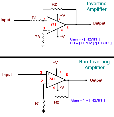
Shown below are the basic inverting and no-inverting amplifier circuits. The gain of the circuit is not dependent on the supply voltage.

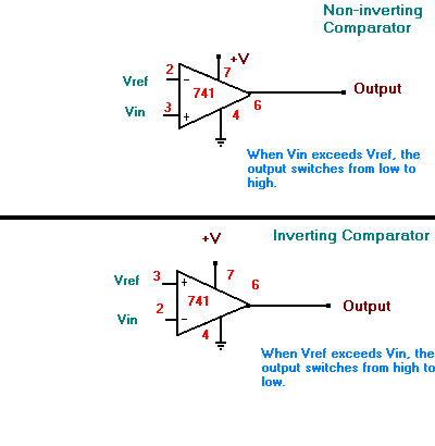
Another common way that opamps are used are in comparator circuits. A comparator circuit will compare the voltage on the two inputs and then making the output high or low. This is accomplished by having one input the voltage reference (Vref) and the other input is the voltage input (Vin). Shown below are the two ways to hook up a comparator circuit.

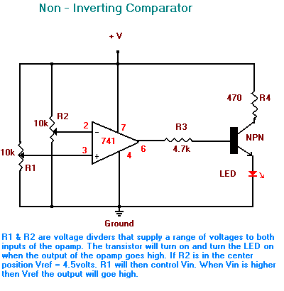
The circuit below shows a basic comparator circuit that you can experiment with.

Sourse:www.home.maine.rr.com


