Arduino and Bluetooth
China's Bluetooth Serail modules are very cheap: 5-10$ per module. You can find them on eBay: Bluetooth RS232, Bluetooth Serial, HC-03, HC-04, HC-05, HC-06.
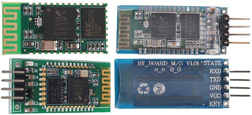
Most modules use a chip BC417 and Flash memory. Specification:
CSR chip: Bluetooth v2.0
Wave band: 2.4GHz-2.8GHz, ISM Band
Protocol: Bluetooth V2.0
Voltage: 3.3 (2.7V-4.2V)
Current: Paring - 35mA, Connected - 8mA
The command set of HC-03 and HC-05 are more flexible than HC-04 and HC-06 modules.
We'll be working with the module HC-06. Circuit diagram:
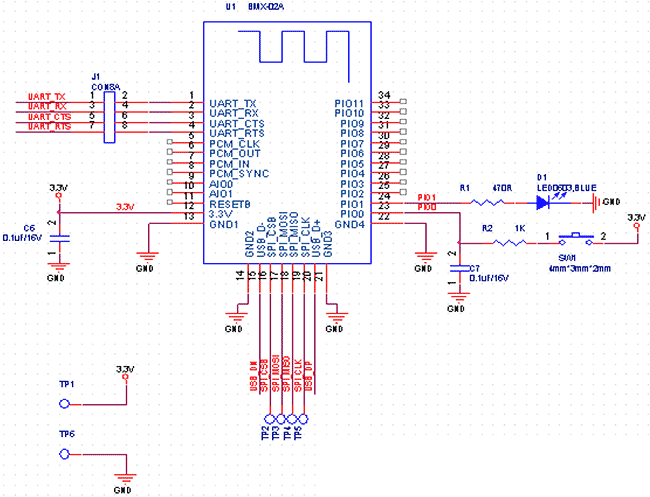
HC-04/HC-06 pins:
UART_TX (pin 1), UART_RX (pin 2), UART_CTS (pin 3), UART_RTS (pin 4) - UART.
3,3V (pin 12) - Power 3.3V.
GND (pin 13) - GND.
PIO1 (pin 24) - LED working mode indicator
HC-03/HC-05 pins:
UART_TX (pin 1), UART_RX (pin 2), UART_CTS (pin 3), UART_RTS (pin 4) - UART.
PIO8 (pin 31) - LED1 working mode indicator.
PIO9 (pin 32) - LED2. Before paired, it output low level. Once the pair is finished, it output high
level.
PIO11 (pin 34) - KEY. Mode switch input. If it is input low level, the module is at paired or communication mode. If
it’s input high level, the module will enter to AT mode.
See PDF documentation.
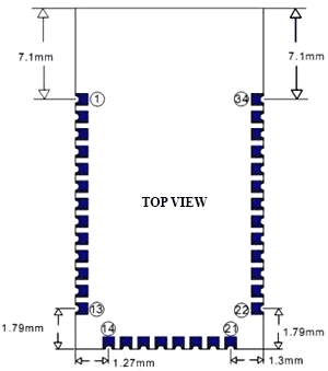
We will connect the Bluetooth module HC-06 to the Arduino Nano V3:
3.3V Arduino pin - to 12 pin HC-06 Bluetooth module
GND Arduino pin - to 13 pin HC-06 Bluetooth module
TX Arduino pin - to 2 pin HC-06 Bluetooth module (RX)
RX Arduino pin - to 1 pin HC-06 Bluetooth module (TX)
Transfer data from the Arduino via Bluetooth
Program to send data from the Bluetooth module to the computer
int cnt = 0;    // Counter

 void setup() {
   Serial.begin(9600);   // Initialization
 }

 void loop() {
   cnt++;
   Serial.print("Hello BB from Arduino! Counter:");  // print message
   Serial.println(cnt);    // print counter
   delay(1000);   // wait 1 sec
 }
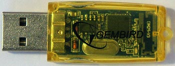
On PC, I use cheapest Bluetooth USB Adapter. After power on, you will be prompted to enter your Bluetooth devices pairing code/password. The default for most Bluetooth devices is 1234. If the pairing is successful, you will see a message.
Now the Bluetooth device and PC are connected.
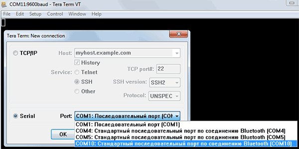
To view the received data we need a Terminal on PC. I use the Tera Term. After starting the program, select the virtual COM-port of the PC Bluetooth device.
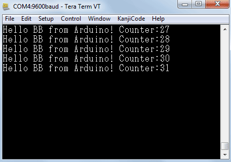
You will see counter from Arduino:
Bi-directional communication between PC and Arduino via Bluetooth
To the diagram, I added the LED connecting it to the 12 pin Arduino, via current-limiting resistor. But you can use build-in LED (13 pin). Our program is very simple:
char incomingByte;  // incoming data
int  LED = 12;      // LED pin

void setup() {
  Serial.begin(9600); // initialization
  pinMode(LED, OUTPUT);
  Serial.println("Press 1 to LED ON or 0 to LED OFF...");
}

void loop() {
  if (Serial.available() > 0) {  // if the data came
    incomingByte = Serial.read(); // read byte
    if(incomingByte == '0') {
       digitalWrite(LED, LOW);  // if 1, switch LED Off
       Serial.println("LED OFF. Press 1 to LED ON!");  // print message
    }
    if(incomingByte == '1') {
       digitalWrite(LED, HIGH); // if 0, switch LED on
       Serial.println("LED ON. Press 0 to LED OFF!");
    }
  }
}
See screenshot:
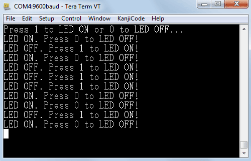
Video:
Android
To work with the Android you will need program: Bluetooth Terminal. Click in menu "Connect a device - Secure" and select our device "BOLUTEK". See video:
Download source code for Arduino
Author: Koltykov A.V.


