Battery heaters in a tube amplifier: A simple battery switch with undervoltage protection
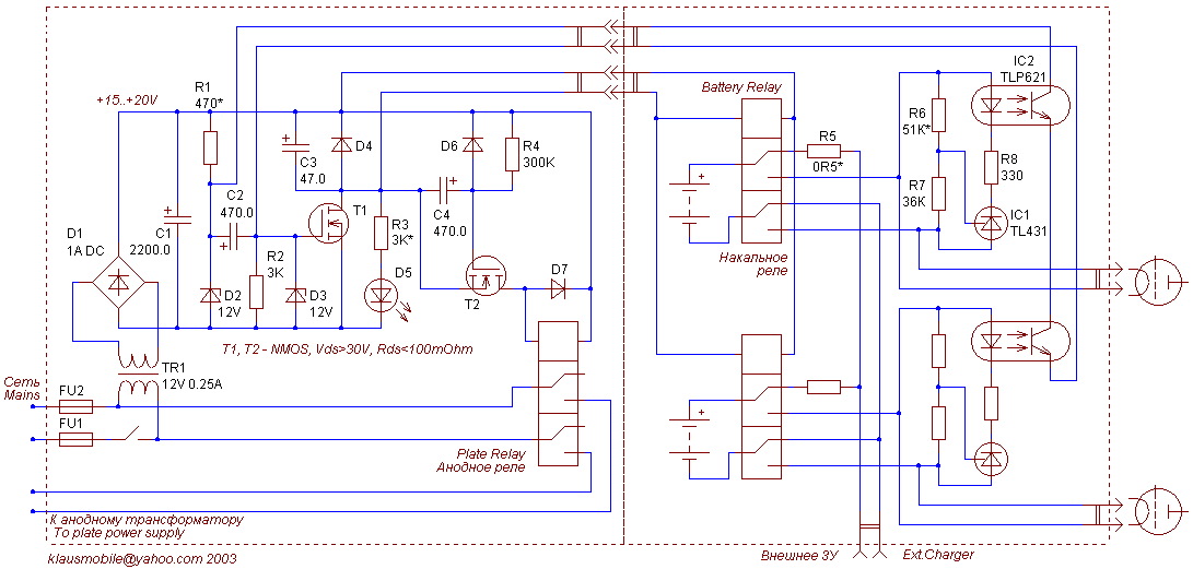
This simple circuit controls 6.3V SLA heater batteries (two batteries are shown, but it is stackable to practically unlimited number of batteries). Batteries are floating in 'on' state, paralleled in 'off' (external charger) state. If any battery voltage falls below threshold for more than 1 second, the circuit latches up in 'off' state, disconnects the batteries and shuts down plate power supply (which is normally controlled through a delay relay). Once in 'off' state, it can be reset to normal only with master mains switch. 1-second 'grace period' set by C2R2 takes care of power-on surge currents that can cause temporary undervoltage.

Circuit is split into 'dirty' (local PS, T1, T2, plate relay) and 'clean' (batteries, heater relays, comparators) circuit boards. Place the 'dirty' board near the existing fuse holder or power switch.
Relays are any small 12V coil relays, they usually have coil resistance in 200..500 Ohm range, switch on at 9..10V and switch off at 2..3V. In off-state, R3D5 indicator current flows through heater relay coils, this current must be small enough to ensure low voltage drop across coils, otherwise they will stay open (R3 value here is for combined coil resistance of 100 Ohm or less).
Plate delay is set (among other factors) by C4, 470 uF roughly translates to 40..60s. Optocouple return path (R1R2) is configured to ensure T1 turn off when optocouple output current is 1mA or less to prevent early turn-off (normal on-state LED current is 8..10mA, normal output current at least 3 mA).
T1, T2 can be any NMOS devices (Rds>0.1 Ohm), with regular, not logic, threshold. Local power supply can be built around a 9V transformer, too, it is sufficient for driving 12V relays (change D2 to a 9V zener).


