klauskorrektor II: External power supply for a tube phono preamplifier (300V, 50mA + 6.3V, 3A max)
(c) klausmobile 2002
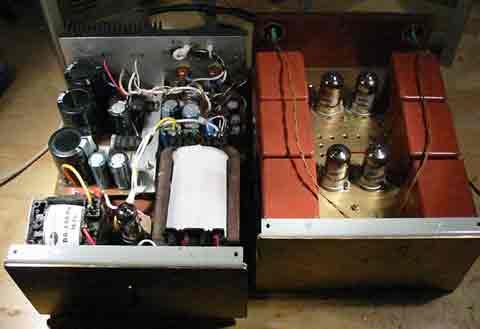
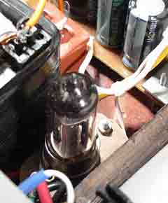
klauskorrektor II audio shematic is the same as in the original klauskorrektor I. Here's a look at the chassis after a few tweaks:
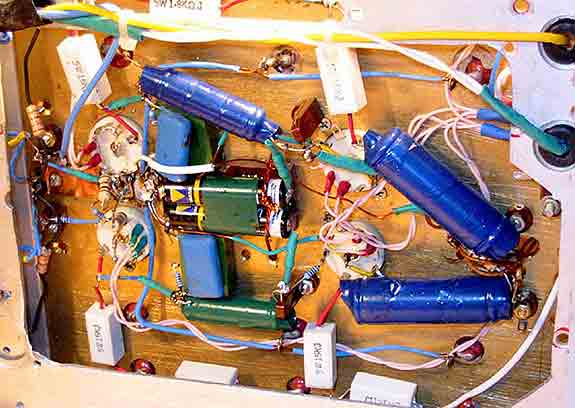
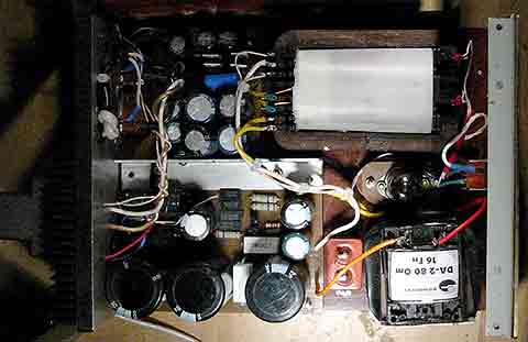
This regulated power supply was built as a simplified outboard version of a PSU in my first phono stage. Replacing hexfreds with tube rectifier eliminates the need for power-on sequencing. Chassis (salvaged from a hospital laser PSU) size is 180W*240D*100H mm with a 125W double-C core power transformer and a 10H/100mA choke inside. Heater and plate regulators are on a same PCB (there's only one heater regulation channel). No exotic components of any kind - a low-cost but ultra-quiet unit. There is additional 120uF of paper capacitors in the phono audio chassis (red bricks on the title photo).
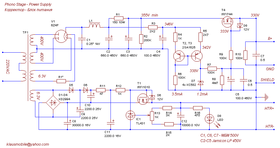
Diodes D1-D4 are any 25V, 10A or more Shottky or Hexfred type; tube rectifier V1 - anything that matches your PIV demands. Zener D7 is actually a string of lower-voltage zeners. You may reduce parts count by replacing a discrete current source (R4-R6, T2-T3) with a 2-terminal current regulator (Motorola 1N5294-1N5309).
Physical ground trace layout on a PCB follows the schematic: transformer center tap goes into C1, then into C2, so it's an upstream line, not a star. Same for heater regulator return trace. Star ground (which is physically a copper eyelet bolted to the chassis wall near the umilical connector) is for joining the end of this trace with heater 'ground', chassis and the screen.
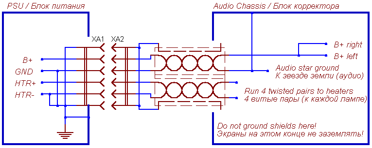
There is only one ground path between two chassis: plate power return (twisted pair). Heater circuit and umbilical screen are grounded to chassis on PSU side only (actually, to an aluminum housing of the XA2 plug, which is bolted to XA1 socket). Do not allow electrical contact between two chassis (this is a perfect ground loop).
I don't have a thoroughly drawn PCB; see the sketch of parts layout and PCB traces here. Power transistors are sandwiched between PCB and heatsink, which is simply a strip of 25*40mm aluminum U-profile (total dissipation around 5W). Use insulated case devices (IRFI***) or take extreme care to insulate T2 from heat sink.
