


Communication between the STM32 and Android via Bluetooth
This article describes the organization of communication via Bluetooth between the microcontroller STM32 (used board STM32 Value Discovery) and any Android-powered device (smartphone, tablet, etc.). As the example shows LED control from the tablet, and sending messages back to Android from STM32 board.
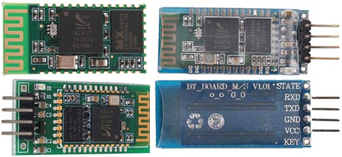
As a Bluetooth module uses cheap Chinese module HC-06, which has been considered in this article.
As an Android device, I used a cheap Chinese tablet "Ainol Aurora" with an external USB-Bluetooth module (because its not have own), connected via USB Host.
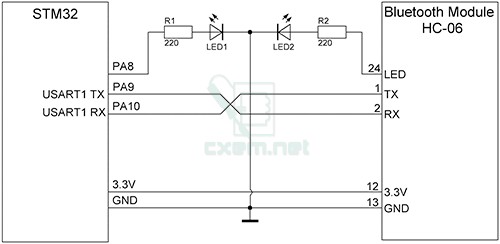
Wiring diagram STM32 Discovery board to the module HC-06 is very simple:
The program for the STM32 was written in the environment CooCox CoIDE, and based on the standard example of STMicroelectronics UART communication..
Source code for STM32:
#include "stm32f10x_usart.h"
#include "stm32f10x_rcc.h"
#include "stm32f10x_gpio.h"
#include "misc.h"

int i;

//ErrorStatus HSEStartUpStatus;

void NVIC_Configuration(void);
void GPIO_Configuration(void);
void USART_Configuration(void);
void USART1_IRQHandler(void);
void UARTSend(const unsigned char *pucBuffer, unsigned long ulCount);

int main(void)
{
	usart_rxtx();
    while(1)
    {

    }
}

/******************************************************************************/
/*            STM32F10x Peripherals Interrupt Handlers                        */
/******************************************************************************/

/**
  * @brief  This function handles USARTx global interrupt request
  * @param  None
  * @retval None
  */
void USART1_IRQHandler(void)
{
    if ((USART1->SR & USART_FLAG_RXNE) != (u16)RESET)
	{
		i = USART_ReceiveData(USART1);
		if(i == '1'){
			GPIO_WriteBit(GPIOA,GPIO_Pin_8,Bit_SET);		// Set '1' on PA8
			UARTSend("LED ON\r\n",sizeof("LED ON\r\n"));	// Send message to UART1
		}
		else if(i == '0'){
			GPIO_WriteBit(GPIOA,GPIO_Pin_8,Bit_RESET);		// Set '0' on PA8
			UARTSend("LED OFF\r\n",sizeof("LED OFF\r\n"));
		}
	}
}

void usart_rxtx(void)
{
    const unsigned char welcome_str[] = " Welcome to Bluetooth!\r\n";

    /* Enable USART1 and GPIOA clock */
    RCC_APB2PeriphClockCmd(RCC_APB2Periph_USART1 | RCC_APB2Periph_GPIOA, ENABLE);

    /* NVIC Configuration */
    NVIC_Configuration();

    /* Configure the GPIOs */
    GPIO_Configuration();

    /* Configure the USART1 */
    USART_Configuration();

    /* Enable the USART1 Receive interrupt: this interrupt is generated when the
         USART1 receive data register is not empty */
    USART_ITConfig(USART1, USART_IT_RXNE, ENABLE);

    /* print welcome information */
    UARTSend(welcome_str, sizeof(welcome_str));
}

/*******************************************************************************
* Function Name  : GPIO_Configuration
* Description    : Configures the different GPIO ports
*******************************************************************************/
void GPIO_Configuration(void)
{
  GPIO_InitTypeDef GPIO_InitStructure;

  /* Configure (PA.8) as output */
  GPIO_InitStructure.GPIO_Pin   = GPIO_Pin_8;
  GPIO_InitStructure.GPIO_Speed = GPIO_Speed_50MHz;
  GPIO_InitStructure.GPIO_Mode  = GPIO_Mode_Out_PP;
  GPIO_Init(GPIOA, &GPIO_InitStructure); // Save

  /* Configure USART1 Tx (PA.09) as alternate function push-pull */
  GPIO_InitStructure.GPIO_Pin = GPIO_Pin_9;
  GPIO_InitStructure.GPIO_Mode = GPIO_Mode_AF_PP;
  GPIO_InitStructure.GPIO_Speed = GPIO_Speed_50MHz;
  GPIO_Init(GPIOA, &GPIO_InitStructure);

  /* Configure USART1 Rx (PA.10) as input floating */
  GPIO_InitStructure.GPIO_Pin = GPIO_Pin_10;
  GPIO_InitStructure.GPIO_Mode = GPIO_Mode_IN_FLOATING;
  GPIO_Init(GPIOA, &GPIO_InitStructure);
}

/*******************************************************************************
* Function Name  : USART_Configuration
* Description    : Configures the USART1
*******************************************************************************/
void USART_Configuration(void)
{
  USART_InitTypeDef USART_InitStructure;

/* USART1 configuration ------------------------------------------------------*/
  USART_InitStructure.USART_BaudRate = 9600;		// Baud Rate
  USART_InitStructure.USART_WordLength = USART_WordLength_8b;
  USART_InitStructure.USART_StopBits = USART_StopBits_1;
  USART_InitStructure.USART_Parity = USART_Parity_No;
  USART_InitStructure.USART_HardwareFlowControl = USART_HardwareFlowControl_None;
  USART_InitStructure.USART_Mode = USART_Mode_Rx | USART_Mode_Tx;

  USART_Init(USART1, &USART_InitStructure);

  /* Enable USART1 */
  USART_Cmd(USART1, ENABLE);
}

/**
  * @brief  Configures the nested vectored interrupt controller.
  * @param  None
  * @retval None
  */
void NVIC_Configuration(void)
{
  NVIC_InitTypeDef NVIC_InitStructure;

  /* Enable the USARTx Interrupt */
  NVIC_InitStructure.NVIC_IRQChannel = USART1_IRQn;
  NVIC_InitStructure.NVIC_IRQChannelPreemptionPriority = 0;
  NVIC_InitStructure.NVIC_IRQChannelSubPriority = 0;
  NVIC_InitStructure.NVIC_IRQChannelCmd = ENABLE;
  NVIC_Init(&NVIC_InitStructure);
}

/*******************************************************************************
* Function Name  : UARTSend
* Description    : Send a string to the UART.
* Input          : - pucBuffer: buffers to be printed.
*                : - ulCount  : buffer's length
*******************************************************************************/
void UARTSend(const unsigned char *pucBuffer, unsigned long ulCount)
{
    //
    // Loop while there are more characters to send.
    //
    while(ulCount--)
    {
        USART_SendData(USART1, (uint16_t) *pucBuffer++);
        /* Loop until the end of transmission */
        while(USART_GetFlagStatus(USART1, USART_FLAG_TC) == RESET)
        {
        }
    }
}
Code is simple: the function GPIO_Configuration () is configured GPIO of STM32 Board, in USART_Configuration() configurable UART, and in the function NVIC_Configuration () is configuration the interrupt.
To send the string to UART uses function UARTSend(). When the data is received by an interrupt occurs and call function USART1_IRQHandler (). Depending on the assumed number 1 or 0, the command on the PA8 board ON or OFF the LED connected to it. And also, there is a transfer string "LED ON" or "LED OFF" back to UART (to Android device)
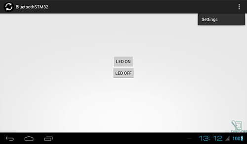
Source code for Android, I will not lead, as he is big and is based on this article, with a few additions. You can download full project in Eclipse. Also, I have attached APK file.
Video:
Download APK application for Android
Download source code and project in CooCox CooIDE for STM32 and Eclipse-project for Android
Author: Koltykov A.V.